Electric connector

A technology of electrical connectors and connecting sections, which is applied in the direction of connections, circuits, and parts of connecting devices, and can solve the problems of conductive terminal insertion angle deviation, affecting terminal transmission quality, and easy deformation of contact sections.

Active Publication Date: 2020-04-14
DEYI PRECISION ELECTRONIC IND CO LTD PANYU
View PDF5 Cites 0 Cited by
  • Summary
  • Abstract
  • Description
  • Claims
  • Application Information

AI Technical Summary

Problems solved by technology

[0002] Today's electronics industry is developing rapidly, so the requirements for the configuration of electrical connectors are getting higher and higher. Conductive terminals, as the most important transmission components, play a key role in the transmission quality of electrical connectors. The terminal is plugged into a preset terminal groove on an insulating body, wherein one end of the conductive terminal is used as a contact section for connecting with an electronic component, and the other end of the conductive terminal is used as a welding section to be welded on a circuit board to realize The signal transmission of the conductive terminal, and the connection section connected between the contact section and the welding section is accommodated in the terminal groove. Generally, the accommodation space in the terminal groove is slightly larger than the overall size of the conductive terminal to facilitate the insertion of the conductive terminal into the terminal groove. The gap between the terminal groove and the conductive terminal is not only easy to make the conductive terminal unstable and easy to loose when the electrical connector is connected, but also because the current conductive terminal tends to be miniaturized and thinner, the conductive terminal is punched in the longitudinal direction. Its contact section is easy to incline relative to the welding section, and it is easy to cause the insertion angle of the conductive terminal to shift (such as oblique insertion) when plugging in, so that there is a risk of friction between the contact section and the inner wall of the terminal groove, resulting in easy deformation of the contact section and affecting the terminal. transmission quality; therefore, to fill the gap between the conductive terminal and the terminal slot, such as figure 1 As shown, generally the front and back surfaces of the conductive terminal 2 are formed with convex shells 2a, 2b, and the convex shells 2a, 2b will be in contact with the inner wall of the terminal groove during the process of inserting the conductive terminal 2 into the terminal groove, thereby ensuring The conductive terminal can be fastened in the terminal groove, but when the conductive terminal 2 is inserted into the terminal groove, when the convex shells 2a, 2b press the inner wall of the terminal groove, a first force in the same direction as the protruding direction of the convex shells 2a, 2b will be generated. , when the inner wall of the terminal groove is squeezed, a first reverse force F1 opposite to the direction of the first force will be generated, so that the entire conductive terminal is inclined towards the direction of the first reverse force F1 during the insertion process ( figure 2 arrow direction), such as figure 2 As shown, the position of the conductive terminal 2 inserted into the terminal groove is not correct, so that the contact section is easy to touch the inner wall of the terminal groove and is displaced and deformed, resulting in a deviation of the contact between the conductive terminal and the electronic component, resulting in poor contact of the electrical connector Phenomenon, affecting the performance stability of the electrical connector

Method used


Image

  • Electric connector
  • Electric connector
  • Electric connector

Examples


Embodiment Construction

[0028] The specific embodiment of the present invention will be further described below in conjunction with accompanying drawing:

[0029] In the description of the present invention, it should be noted that the terms "center", "upper", "lower", "left", "right", "vertical", "horizontal", "inner", "outer" etc. The indicated orientation or positional relationship is based on the orientation or positional relationship shown in the drawings, and is only for the convenience of describing the present invention and simplifying the description, rather than indicating or implying that the indicated position or element must have a specific orientation, and must have a specific orientation. construction and operation, therefore, should not be construed as limiting the invention.

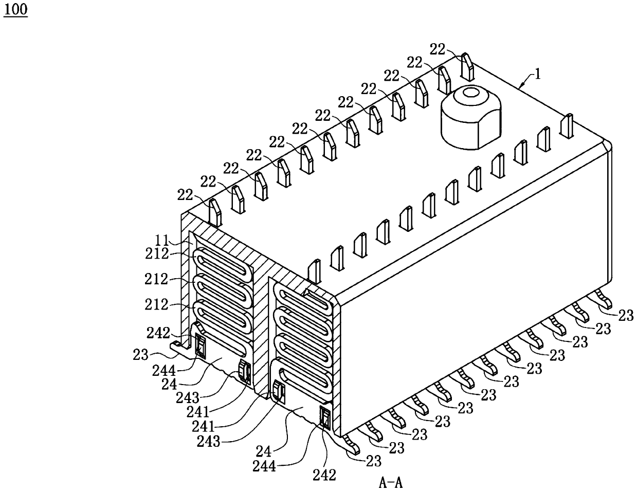
[0030] like image 3 As shown, it is an electrical connector 100 of the present invention, which includes a rectangular insulating body 1, and the insulating body 1 is formed with a plurality of terminal slots...


PUM


Abstract

The invention discloses an electric connector. According to the invention, a conductive terminal is provided with at least two pairs of protruding parts, the two convex parts of each pair of protruding parts protrude oppositely along the thickness direction of the conductive terminal, the two convex parts are arranged in a mirror image manner along the width direction of the conductive terminal bytaking the central axis of the conductive terminal connecting part as the center; the convex partss extrude the terminal grooves to correspondingly generate counter-acting force to be propped againsteach other, the position of the conductive terminal in the terminal groove is not obliquely, therefore, the problem of poor contact of the electric connector due to the fact that the conductive terminal is obliquely inserted into the terminal groove or the conductive terminal is inclined due to the protruding parts in the inserting process is solved, and the conductive terminal is not prone to displacement after being inserted into the terminal groove.

Description

【Technical field】 [0001] The invention relates to an electrical connector, in particular to an electrical connector used for connecting circuit boards and electronic components. 【Background technique】 [0002] Today's electronics industry is developing rapidly, so the requirements for the configuration of electrical connectors are getting higher and higher. Conductive terminals, as the most important transmission components, play a key role in the transmission quality of electrical connectors. The terminal is plugged into a preset terminal groove on an insulating body, wherein one end of the conductive terminal is used as a contact section for connecting with an electronic component, and the other end of the conductive terminal is used as a welding section to be welded on a circuit board to realize The signal transmission of the conductive terminal, and the connection section connected between the contact section and the welding section is accommodated in the terminal groove...

Claims


Application Information

Patent Timeline
IPC IPC(8): H01R12/71H01R13/02H01R13/24H01R13/40
CPCH01R12/716H01R13/02H01R13/2414H01R13/40
Inventor 冯晓曹永金
Owner DEYI PRECISION ELECTRONIC IND CO LTD PANYU
Why Eureka
Try Eureka