A kind of ultra-thin coil tooling fixture, preparation method and preparation equipment
A tooling, jig and coil technology, applied in coil manufacturing and other directions, can solve the problems of cost waste, high manufacturing cost, low coil production efficiency, etc., and achieve the effect of reducing process links, saving equipment costs, and improving production efficiency
- Summary
- Abstract
- Description
- Claims
- Application Information
AI Technical Summary
Problems solved by technology
Method used
Image
Examples
Embodiment 1
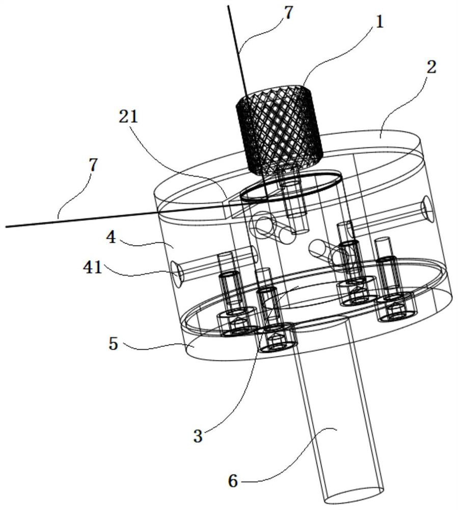
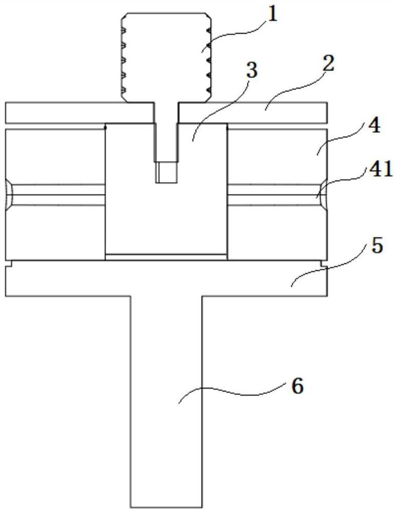
[0048] see figure 1 and figure 2 , the application provides an ultra-thin coil tooling fixture, including: a locking member 1, a cover plate 2, a mold core 3, a mold sleeve 4, a bottom plate 5, and a heat conducting member;
[0049] One end of the locking part 1 passes through the cover plate 2 and is detachably connected to the mold core 3. The mold sleeve 4 is sleeved on the mold core 3. The peripheral side of the mold sleeve 4 is provided with a locking and unlocking mold sleeve 4 and the mold core 3. The top wire at the middle position, the bottom plate 5 is fixedly connected to the side of the mold case 4 away from the cover plate 2, and the mold core 3 is connected to the external heat source through the heat conducting member; wherein,
[0050] In the coil winding state, the mold cover 4 cooperates with the mold core 3 through the top wire to adjust and lock the distance between the cover plate 2 and the mold cover 4, wherein the distance between the cover plate 2 and...
Embodiment 2
[0063] see Figure 6 , This embodiment provides a method for preparing an ultra-thin coil based on Embodiment 1, using any ultra-thin coil tooling fixture as in Embodiment 1 to prepare the coil, and the method includes the following steps:
[0064] S1: Adjust and lock the distance between the cover plate and the mold sleeve to limit the width of the coil winding;
[0065] S2: Between the cover plate and the mold sleeve, select a single-strand or multi-strand wire to wind the coil around the mold core, wherein, during the coil winding process, the wound coil is heated through the heat conduction of the mold core, so that the coil Adjacent wires are glued to each other;
[0066] S3: After the winding of the coil is completed, unlock the distance between the mold sleeve and the mold core, and press the wound coil by pressing the cover plate and / or the bottom plate, so that the cross-sectional thickness of the wound coil is flat, wherein , During the coil pressing process, the w...
Embodiment 3
[0074] This embodiment provides an ultra-thin coil preparation device based on Embodiment 1, including: any ultra-thin coil tooling fixture in Example 1, and an intelligent numerical control device that cooperates with the tooling tool for coil preparation.
[0075] Due to the ultra-thin coil tooling fixture based on Embodiment 1, the ultra-thin coil preparation equipment of this embodiment has the following technical advantages:
[0076] 1) In this embodiment, the position between the clamping sleeve and the mold core is locked or unlocked by the top screw, so that the distance between the cover plate and the mold sleeve can be changed, and it is suitable for coil wires of different sizes to be wound into coils , realize the purpose of producing multiple coils with one jig, and achieve the technical effect of strong versatility;
[0077]2) In this embodiment, when the jackscrew is locked, the winding groove is formed by the mold core, the mold sleeve, and the cover plate, whi...
PUM
 Abstract
Description
Claims
Application Information
 - R&D
- Intellectual Property
- Life Sciences
- Materials
- Tech Scout
- Unparalleled Data Quality
- Higher Quality Content
- 60% Fewer Hallucinations
Browse by: Latest US Patents, China's latest patents, Technical Efficacy Thesaurus, Application Domain, Technology Topic, Popular Technical Reports.
© 2025 PatSnap. All rights reserved.Legal|Privacy policy|Modern Slavery Act Transparency Statement|Sitemap|About US| Contact US: help@patsnap.com


