Wavefront detection device and method for edge sub-mirror in spliced mirror

A technology of wavefront detection and sub-mirror, which is applied in the direction of measuring devices, machine/structural component testing, optical instrument testing, etc.

Active Publication Date: 2020-04-14
INST OF OPTICS & ELECTRONICS - CHINESE ACAD OF SCI
View PDF7 Cites 3 Cited by
  • Summary
  • Abstract
  • Description
  • Claims
  • Application Information

AI Technical Summary

Problems solved by technology

[0005] The present invention provides a wavefront detection device and method for edge sub-mirrors in a splicing mirror. Before nine sub-mirrors are co-phased together, it is first necessary to ensure that the wavefront of each sub-mirror meets the requirements. The present invention solves eight of them. Wavefront detection problem of edge sub-mirror

Method used


Image

  • Wavefront detection device and method for edge sub-mirror in spliced mirror
  • Wavefront detection device and method for edge sub-mirror in spliced mirror
  • Wavefront detection device and method for edge sub-mirror in spliced mirror

Examples


Embodiment Construction

[0028] The present invention will be further described below in conjunction with the accompanying drawings and specific embodiments.

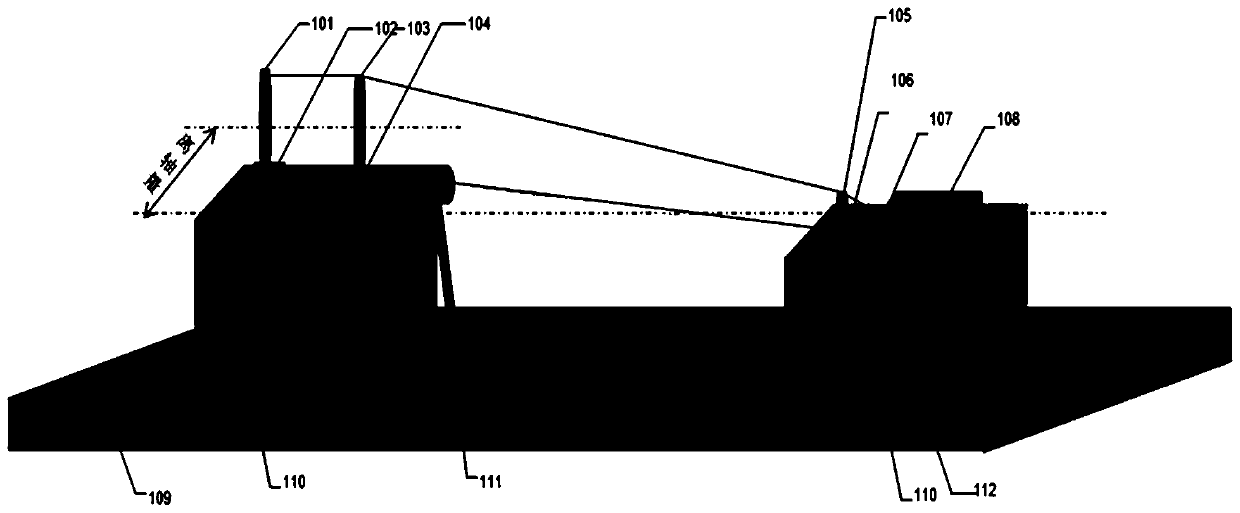
[0029] Such as figure 1 As shown, a wavefront detection device of the edge sub-mirror in the splicing mirror uses an interferometer and a laser tracker in combination, and uses a computational hologram to compensate for aberrations to detect the wavefront of the edge sub-mirror in the splicing mirror. The device includes a high-precision flat mirror 101, a lifting frame 102, a measured edge mirror 103, a tilt adjustment device 104, a calculation hologram 105, a small five-dimensional adjustment table 106, a standard lens 107, an interferometer 108, and a vibration isolation platform 109 , Five-dimensional adjustment table 110, laser tracker 111, target ball 112.

[0030] Wherein, the light emitted in the interferometer 108 passes through the standard lens 107, the calculation hologram 105, the measured edge sub-mirror 103, and is reflected on...


PUM


Abstract

The invention discloses a wavefront detection device and method for an edge sub-mirror in a spliced mirror. An interferometer and a laser tracker are combined for use; the wavefront of the edge sub-mirror in the spliced mirror is detected by compensating aberration through a computer-generated hologram sheet; the wavefront detection device comprises a high-precision plane mirror, a lifting frame,the detected edge sub-mirror, an inclination adjustment device, the computer-generated hologram sheet, a small five-dimensional adjustment table, a standard lens, the interferometer, a vibration isolation platform, a five-dimensional adjustment table, the laser tracker and a target ball. A space coordinate system of the interferometer, the measured edge sub-mirror and the plane mirror is established by using the laser tracker; and the computer-generated hologram sheet is palced to be aligned with the interferometer, the interferometer and the computer-generated hologram sheet are taken as a whole, the pitch and inclination of the whole are finely adjusted to form an auto-collimation light path, and adjustment is carried out until an aberration item in a wavefront detection result of the interferometer is minimum, thereby obtaining the wavefront detection result of the detected edge sub-mirror.

Description

technical field [0001] The invention belongs to the field of wavefront detection, and in particular relates to a wavefront detection device and method for edge sub-mirrors in splicing mirrors. Background technique [0002] Traditional optical astronomical telescopes generally use reflective optical imaging systems. As the aperture increases, they will face the problems of tight surface tolerance, heavy weight, and high cost, which severely limit their application in astronomy. Compared with ordinary reflectors, diffractive optical elements represented by phase-type Fresnel lenses have relatively loose surface tolerances and low weight and can be used in future ultra-large-aperture optical telescopes. Limited by the current level of micro-optical element processing technology, it is difficult for the Fresnel lens used for imaging to reach the meter level. The only way to achieve a large aperture is through splicing technology. The splicing mirror is composed of multiple sub-...

Claims


Application Information

Patent Timeline
Patent Type & Authority Applications(China)
IPC IPC(8): G01M11/02
CPCG01M11/0207G01M11/0271
Inventor 罗倩吴时彬汪利华杨伟范斌
Owner INST OF OPTICS & ELECTRONICS - CHINESE ACAD OF SCI
Why Eureka
Try Eureka