A stackable light pole rack

A placing rack and stacking technology, applied in the field of stacking light pole placement racks, can solve the problems of light pole collision damage, light pole rolling, falling, etc., so as to avoid force shaking and mutual collision, and avoid rolling and collision. problems, the effect of improving the utilization of space

Active Publication Date: 2022-05-24
湖州华普钢杆制造有限公司
View PDF16 Cites 0 Cited by
  • Summary
  • Abstract
  • Description
  • Claims
  • Application Information

AI Technical Summary

Problems solved by technology

[0002] Since most of the street light poles on the market are cylindrical or regular polygonal, when a truck transports such light poles, the light poles will roll back and forth under the action of the steering force, resulting in damage to the light poles due to collision and damage. With the risk of falling
The current solution to this kind of problem is to bind ropes on the surface of the light pole, and connect the ropes to the pallet of the truck, and avoid the problem of rolling or offset through the limit of the ropes; but this fixing method is not firm. In the actual transportation process, there are often problems that the rope is loose and the light pole rolls
And when the rope is connected, it can only fix the outside of the light poles, and the adjacent light poles only rely on extrusion to limit the position, resulting in collisions between adjacent light poles during the transportation of the truck, which increases the number of light poles. Rod collision damage
In addition, due to the unique shape of the multi-head lamp and the combination lamp, there will be a lot of special-shaped supports distributed around one end of the light pole in a ring, and these support will be in direct contact with the ground when placed, and need to bear the load caused by the light pole. The pressure from the bearing, resulting in pressure damage and collision damage to the bearing
The increase in the space occupied by the support part will further increase the risk of collision between adjacent light poles, making it difficult for the light poles of multi-head lights and combination lights to maintain good integrity and fullness of surface paint after long-distance transportation. Manually touch up the paint after the light pole is scratched
Therefore, the existing fixing methods for light poles will cause rolling, collision and compression deformation of light poles during transportation

Method used


Image

  • A stackable light pole rack
  • A stackable light pole rack

Examples


Embodiment Construction

[0020] The present invention will be further described below in conjunction with the accompanying drawings and embodiments, but not as a basis for limiting the present invention.

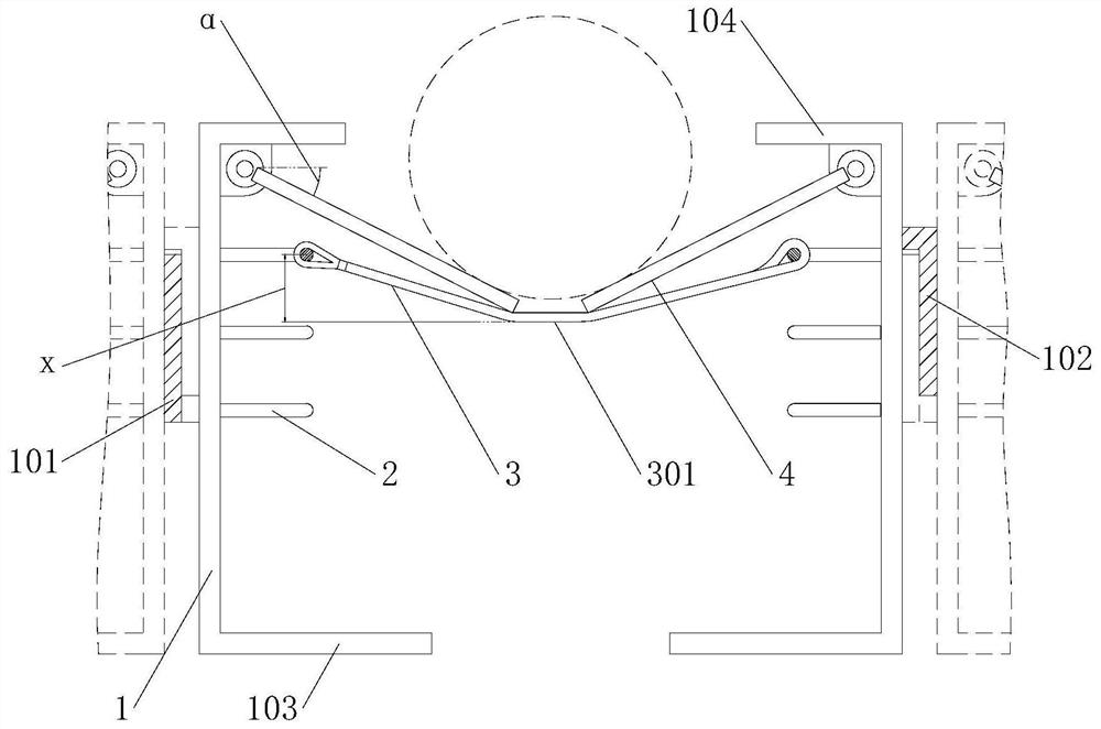
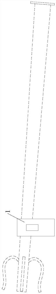
[0021] Example. A stacked light pole placement frame, constituted as figure 1 As shown, it includes a left-right symmetrical placement frame 1, and a plurality of installation ring groups are arranged at intervals from top to bottom in the placement frame 1, and each group of installation ring groups includes installation rings 2 respectively arranged on the inner sides of the two placement frames 1, The two installation rings 2 of one group of installation ring groups are connected to each other through a steel wire rope 3, and the steel wire rope 3 is wound on the installation ring 2 in multiple turns. The bottom of the plate 4 is attached to the wire rope 3; the outer wall of the shelf 1 on one side is provided with a buckle groove 101, and the outer wall of the shelf 1 on the other side is prov...


PUM


Abstract

The invention discloses a stacking lamp pole placement rack, comprising a placement rack (1) symmetrically arranged left and right, a plurality of mounting ring groups are arranged in the placement rack (1) at intervals from top to bottom, and each mounting ring group includes The mounting rings (2) are respectively arranged on the inner sides of the two placing racks (1), wherein the two mounting rings (2) of a set of mounting rings are connected to each other by a wire rope (3), and the wire rope (3) is wound in multiple turns On the mounting ring (2), the placing frame (1) above the mounting ring (2) is rotatably connected to the limit plate (4), the bottom of the limit plate (4) and the wire rope (3) are attached to each other; A buckle groove (101) is provided on the outer wall of the placing rack (1), and a buckle plate (102) that cooperates with the buckle groove (101) is provided on the outer wall of the placing rack (1) on the other side. The invention can effectively avoid rolling, collision and compression deformation of the light pole during transportation.

Description

technical field [0001] The invention relates to a light pole placement frame, in particular to a stacked light pole placement frame. Background technique [0002] Since most of the street light poles on the market are cylindrical or regular polygonal, when a truck transports such light poles, the light poles will roll back and forth under the action of the steering force, resulting in damage to the light poles due to collision and damage. There is a danger of falling. The current solution to this kind of problem is to bind ropes on the surface of the light pole, and connect the ropes to the pallet of the truck, and avoid the problem of rolling or offset through the limit of the ropes; but this fixing method is not firm. In the actual transportation process, the problem that the rope is loosened and the light pole rolls often occurs. And when the rope is connected, it can only fix the outside of the light poles, and the adjacent light poles only rely on extrusion to limit t...

Claims


Application Information

Patent Timeline
Patent Type & Authority Patents(China)
IPC IPC(8): B65D61/00B65D85/20B65D81/07
CPCB65D61/00B65D85/20B65D81/07
Inventor 黄永林
Owner 湖州华普钢杆制造有限公司
Why Eureka
Try Eureka