
Welding device, and burn-back control device and method

A control method and control device technology, applied in welding equipment, welding accessories, manufacturing tools, etc., can solve the problem of large distance between the tip of the welding wire and the welding workpiece, and achieve the effect of improving the success rate of arc ignition

Active Publication Date: 2020-04-14
PANASONIC WELDING SYST TANGSHAN
View PDF19 Cites 1 Cited by
  • Summary
  • Abstract
  • Description
  • Claims
  • Application Information

AI Technical Summary

Problems solved by technology

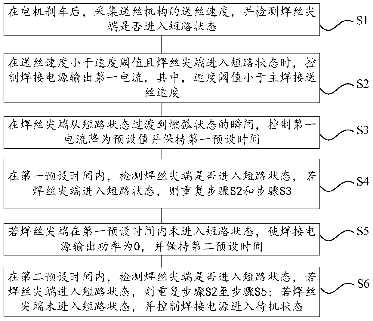
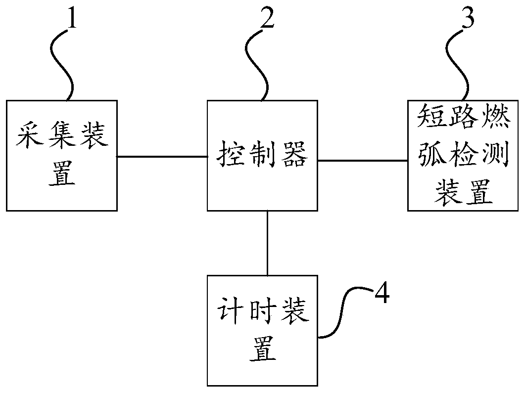
[0005] The purpose of the present disclosure is to provide a welding device, a burnback control device and a burnback control method, which can improve the success rate of arc striking, and at the same time solve the problem that the distance between the tip of the welding wire and the welding workpiece is too large after the burnback is completed

Method used


Image

  • Welding device, and burn-back control device and method
  • Welding device, and burn-back control device and method
  • Welding device, and burn-back control device and method

Examples


Embodiment Construction

[0047] Example embodiments will now be described more fully with reference to the accompanying drawings. Example embodiments may, however, be embodied in many forms and should not be construed as limited to the examples set forth herein; rather, these embodiments are provided so that this disclosure will be thorough and complete, and will fully convey the concept of example embodiments to the Those skilled in the art. The described features, structures, or characteristics may be combined in any suitable manner in one or more embodiments. In the following description, numerous specific details are provided in order to give a thorough understanding of embodiments of the present disclosure. However, one skilled in the art will appreciate that the technical solutions of the present disclosure may be practiced without one or more of the specific details, or that other methods, materials, devices, etc. may be employed. In other instances, well-known technical solutions have not be...


PUM


Abstract

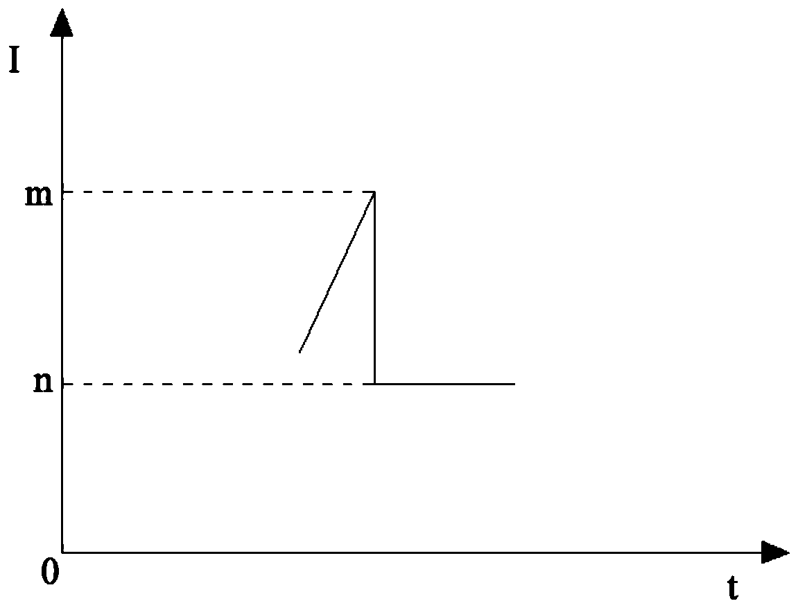
The invention provides a welding device, a burn-back control device and a burn-back control method. The burn-back control method can comprise the steps: step S1, after a motor is braked, the wire feeding speed of a wire feeding mechanism is collected, and whether the tip end of a welding wire enters a short-circuit state or not is detected; step S2, when the wire feeding speed is smaller than a speed threshold value and the tip end of the welding wire enters the short-circuit state, a welding power source is controlled to output first current, and the speed threshold value is smaller than themain welding wire feeding speed; and step S3, at the moment when the tip of the welding wire is transited from the short-circuit state to an arcing state, the first current is controlled to be reducedto a preset value and kept for first preset time. The arc striking success rate can be increased, and the problem that the wire sticking risk exists due to the fact that the distance between the tipof the welding wire and a welding workpiece is too large or too small after burn-back is finished is solved.

Description

technical field [0001] The present disclosure relates to the field of welding technology, in particular to a welding device, a burnback control device and a burnback control method. Background technique [0002] With the development of modern industrial technology and the improvement of the level of industrial manufacturing, people have higher and higher requirements for welding quality. Due to the good welding quality of MIGMA welding, it is widely used in industrial production. [0003] The arc ignition process of MIGMA welding is as follows: after the welding starts, the welding wire starts to be sent out, and the tip of the welding wire contacts the welding workpiece. Under the action of the welding current, the resistance heat of the welding wire heats the welding wire, which in turn causes the tip of the welding wire to discharge and form an arc . After the welding is completed, it needs to be burned back. However, the existing burn-back process will lead to the for...

Claims


Application Information

Patent Timeline
Patent Type & Authority Applications(China)
IPC IPC(8): B23K9/00B23K9/133B23K9/32
CPCB23K9/00B23K9/133B23K9/32
Inventor 陈立宁张立伟赵永键温培银
Owner PANASONIC WELDING SYST TANGSHAN
Learn More