
plasma jet device

A spray device and plasma technology, applied in the directions of plasma and electrical components, can solve the problems of large laser trigger structure size, increased trigger discharge delay, complex laser system, etc., and achieve good trigger effect and short turn-on delay. , the effect of high flexibility

Active Publication Date: 2021-06-01
XI AN JIAOTONG UNIV
View PDF8 Cites 0 Cited by
  • Summary
  • Abstract
  • Description
  • Claims
  • Application Information

AI Technical Summary

Problems solved by technology

[0004] 1. The structure size of laser trigger technology is large, and the laser system is very complicated, which is only feasible in MV-level gas switches
[0005] 2. The electric pulse field distortion trigger technology has requirements for the voltage range of the main gap and the parameters of the trigger pulse waveform. The trigger pulse amplitude usually requires tens to hundreds of kV, the leading edge of the pulse is tens of ns, and the working coefficient of the main gap (main The ratio of the working voltage of the gap to the DC self-breakdown voltage) usually cannot be less than 0.6, otherwise the trigger discharge delay will increase sharply. When the working coefficient is less than 0.5, the electric pulse field distortion trigger mode is almost no longer capable of triggering the main gap conduction The ability cannot meet the technical requirements that the fast switch can be effectively triggered even if the working voltage is lower than 40%.

Method used


Image

  • plasma jet device

Examples


Embodiment Construction

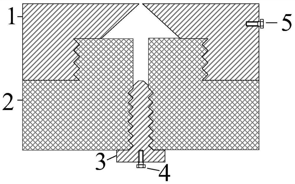
[0029] The following will refer to the attached figure 1 Specific examples of the present invention are described in more detail. Although specific embodiments of the invention are shown in the drawings, it should be understood that the invention may be embodied in various forms and is not limited to the embodiments set forth herein. Rather, these embodiments are provided for more thorough understanding of the present invention and to fully convey the scope of the present invention to those skilled in the art.

[0030] It should be noted that certain terms are used in the specification and claims to refer to specific components. Those skilled in the art should understand that they may use different terms to refer to the same component. The specification and claims do not use differences in nouns as a way of distinguishing components, but use differences in functions of components as a criterion for distinguishing. "Includes" or "comprises" mentioned throughout the specifica...


PUM


Abstract

Disclosed is a plasma injection device. In the plasma injection device, the annular ground electrode is provided with a cavity with an injection hole, and the injection hole is located on the upper surface of the annular ground electrode. As it approaches the direction of the injection hole, the The size of the cavity gradually becomes smaller, and the cavity is provided with a first internal thread in the direction away from the spray hole. The trigger chamber includes a central through hole and a protrusion, the central through hole is provided with a second internal thread, and the protrusion The side surface of the part is provided with a first external thread, and the first external thread is threadedly connected with the first internal thread to assemble the trigger cavity and the annular ground electrode, wherein the protrusion is fitted in the cavity, The trigger electrode includes a frustum at the top and a second external thread on the side surface, the second external thread is threadedly connected to the second internal thread to assemble the trigger electrode and the trigger cavity, wherein the frustum It is lower than the upper surface of the protrusion by a predetermined distance and higher than the bottom surface of the ring-shaped ground electrode.

Description

technical field [0001] The invention relates to the technical field of rapid protection of power systems, in particular to a plasma injection device. Background technique [0002] With the development of fast control and protection of power systems, the requirements for fast action of switchgear are getting higher and higher. Due to the large volume, complex structure and many transmission links of the mechanical operating mechanism, the shortening of the action time is greatly restricted. In some special application fields, it can no longer fully meet the use requirements. Therefore, according to the pulse power theory, relevant researchers have developed gas switches based on different triggering technologies as a new type of fast protection switch system. The action time of the system is short, and the cooperation with traditional mechanical switches can realize the rapid protection of UHV DC transmission lines. [0003] However, the current triggering technologies are ...

Claims


Application Information

Patent Timeline
Patent Type & Authority Patents(China)
IPC IPC(8): H05H1/52
CPCH05H1/52
Inventor 刘轩东李晓昂张乔根
Owner XI AN JIAOTONG UNIV
Learn More