


Quick Research
Generate reliable direction feasibility study reports for your R&D in just a few steps.

Technical Q&A
Discover and master advanced knowledge NOW. Basics, ideas, possibilities, all at once.

Find Solutions
As an expert in R&D theories, this can generate solutions to your technical problems instantly.

Evaluate Feasibility
Analyze your overall solution with one click, know your potential R&D risks in advance.

Monitor Landscape
Get weekly tech updates, stay abreast of the latest tech innovations and key insights.
Sound device
A sound-generating device and magnetic bowl technology, applied in the direction of sensors, electrical components, transducer diaphragms, etc., can solve the problems of reducing vibration reliability, easy damage to the diaphragm, and limited vibration stiffness of the diaphragm to achieve high vibration reliability , the effect of improving stiffness
- Summary
- Abstract
- Description
- Claims
- Application Information
AI Technical Summary
Problems solved by technology
Method used
Image

Examples
Embodiment approach 1
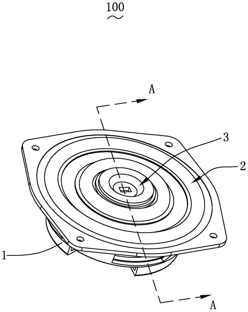
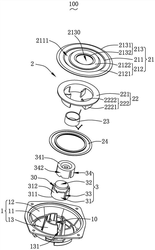
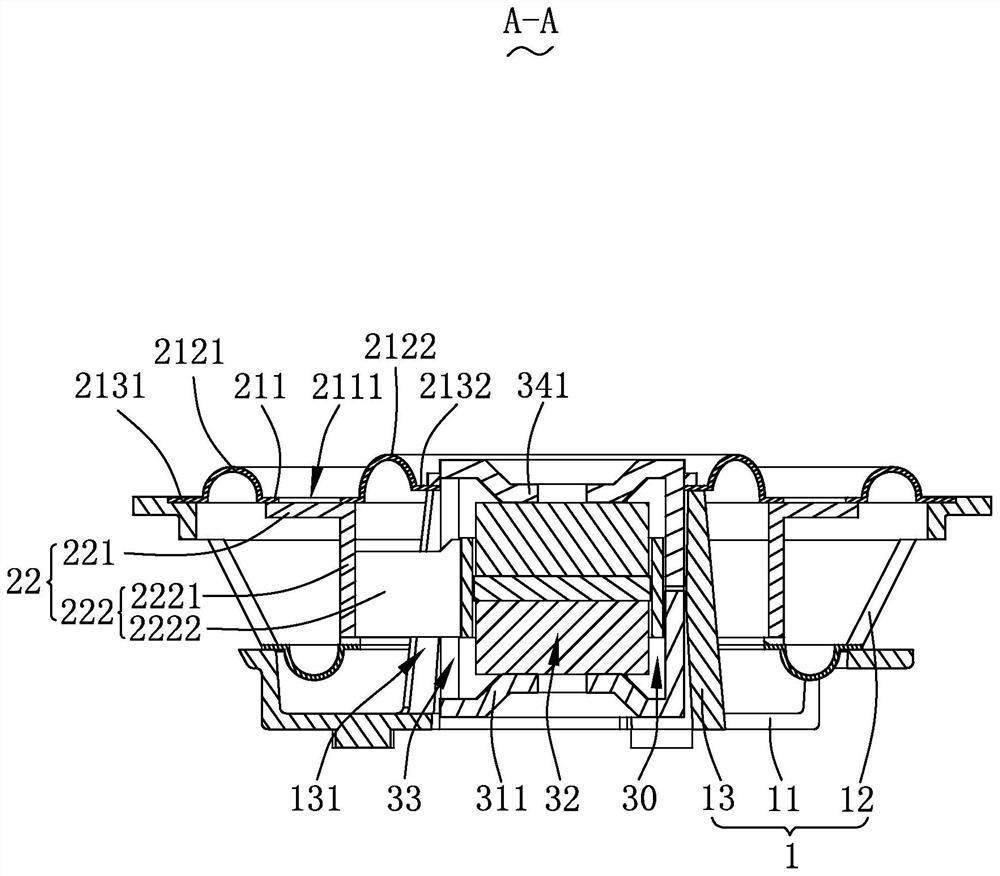
[0042] Please also see Figure 1-3 As shown, the present invention provides a sound-generating device 100 , which includes a basin frame 1 , a vibrating system 2 and a magnetic circuit system 3 with a magnetic gap 30 . The vibration system 2 and the magnetic circuit system 3 are respectively fixedly supported on the basin frame 1, and the magnetic circuit system 3 is used to drive the vibration system 2 to vibrate and produce sound.
[0043] It should be noted that the specific structural form of the pot frame 1 is not limited, and it can be specifically set according to the actual use situation. For example, in this embodiment, the pot frame 1 includes a bottom plate 11, which is bent from the outer periphery of the bottom plate 11. The outer wall 12 is bent and extended and the inner wall 13 is bent and extended from the inside of the bottom plate 11. The outer wall 12 is arranged around the inner wall 13 and spaced from each other; of course, in practical applications, it i...
Embodiment approach 2
[0071] see Figure 4 As shown, the structure of the sound-generating device 100a in the second embodiment is basically the same as that in the first embodiment, and the same parts between the two will not be described one by one. Here, the second fixed part in the diaphragm of the two The structural forms and their positional connections are different. The following describes the specific structure:
[0072] In the second embodiment, the second fixing part 2132a of the diaphragm 21a is attached and fixed to the end of the second magnetic bowl bottom wall 341a away from the first magnetic bowl 31a, and by fixing the second fixing part 2132a to the upper end surface 3411a, effectively The bonding area between the second fixing part 2132a and the magnetic circuit system 3a is increased, so that the bonding between the two is firmer, and the reliability of the second fixing part 2132a is improved, thereby improving the vibration of the diaphragm 21a reliability.
[0073] More pr...
Embodiment approach 3
[0075] see Figure 5-6 As shown, the structure of the sound-generating device 100b in the third embodiment is basically the same as that in the first embodiment, and the same parts between the two will not be described one by one. Here, the second fixed part in the diaphragm of the two The location and connection relationship of each is different, and the following description will be combined with the specific structure:
[0076] In Embodiment 3, the basin frame 1b includes a bottom plate 11b, an outer wall 12b bent and extended from the outer periphery of the bottom plate 11b, and an inner wall 13b bent and extended from the inner side of the bottom plate 11b. The outer walls 12b are arranged around the inner wall 13b and spaced apart from each other.
[0077] The inner wall 13b encloses the accommodation space 10b, and the magnetic circuit system 3b is fixedly accommodated in the accommodation space 10b. Specifically, the magnetic circuit system 3b is fixed to the inner wal...
PUM
 Abstract
Description
Claims
Application Information
 - R&D Engineer
- R&D Manager
- IP Professional
- Industry Leading Data Capabilities
- Powerful AI technology
- Patent DNA Extraction
Browse by: Latest US Patents, China's latest patents, Technical Efficacy Thesaurus, Application Domain, Technology Topic, Popular Technical Reports.
© 2024 PatSnap. All rights reserved.Legal|Privacy policy|Modern Slavery Act Transparency Statement|Sitemap|About US| Contact US: help@patsnap.com