Eureka AIR delivers breakthrough ideas for toughest innovation challenges, trusted by R&D personnel around the world.

Hall proximity switch structure

A Hall proximity switch and rigid board technology, applied in the field of sensors, can solve the problems of inability to expand the sensing distance, limited magnet size, weight and sensor test accuracy of Hall proximity switches, so as to improve mechanical resistance and sensing accuracy , volume reduction, and the effect of improving test accuracy

Active Publication Date: 2020-04-10
SHANDONG INST OF AEROSPACE ELECTRONICS TECH
View PDF6 Cites 1 Cited by
  • Summary
  • Abstract
  • Description
  • Claims
  • Application Information

AI Technical Summary

Problems solved by technology

[0005] Therefore, the traditional Hall proximity switch is limited by the size, weight and sensor test accuracy of the magnet, and can only be used in limit control within 10mm, and cannot expand the sensing distance

Method used


Image

  • Hall proximity switch structure
  • Hall proximity switch structure
  • Hall proximity switch structure

Examples


Embodiment

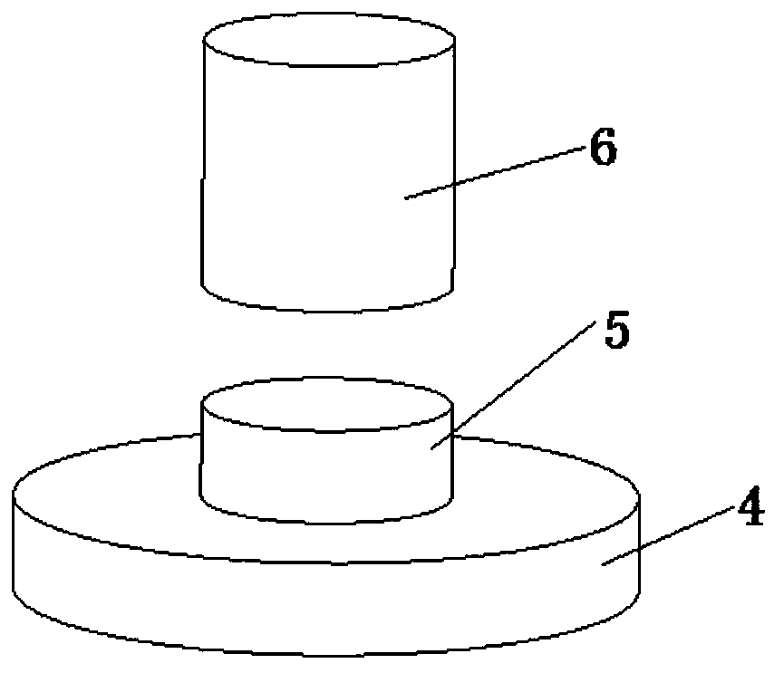
[0025] Such as Figure 1 to Figure 5 As shown, a Hall proximity switch structure includes a printed circuit board, a magnetic field amplifier, and a skeleton shell 7 .

[0026] The printed circuit board includes a first rigid board 1 welded with an induction chip and a second rigid board 2 welded with a processing circuit, the first rigid board 1 is used as an inductive probe of a sensor, and the first rigid board 1 and The second rigid boards 2 are connected through a flexible board 3 , and the flexible board 3 is used for electrical connection between the first rigid board 1 and the second rigid board 2 .

[0027] The magnetic field amplifier is arranged inside the frame housing 7, and is wrapped and fixed by the frame housing 7. The magnetic field amplifier is made of a soft magnetic material, and the magnetic field amplifier includes a first magnetic collecting post 4 and a second magnetic collecting post 5. And the third magnetic collection column 6, the diameter of the ...


PUM


Abstract

The invention discloses a Hall proximity switch structure which comprises a printed circuit board, a magnetic field amplifier and a framework shell. The printed circuit board comprises a first rigid board welded with an induction chip and a second rigid board welded with a processing circuit, and the first rigid board and the second rigid board are connected through a flexible board. The magneticfield amplifier, the first rigid plate and the flexible plate are arranged in the framework shell; the first rigid plate is inserted into an internal air gap of the magnetic field amplifier, the end,connected with the second rigid plate, of the flexible plate penetrates out of the framework shell, and the second rigid plate is fixed to the outer wall of the framework shell. According to the invention, the size and weight of the external magnetic steel can be reduced, the test precision of the sensor is improved, and the induction distance of the Hall proximity switch can be extended to more than 50 mm.

Description

technical field [0001] The invention relates to the field of sensors, in particular to a Hall proximity switch structure. Background technique [0002] Hall proximity switch is an electronic switch with limit control function. Its working principle is that the magnetic field signal is generated by the external magnetic steel, and the sensor body senses the magnetic field signal. When the relative position of the sensor body and the magnetic steel reaches the sensing distance, the sensor output electric signal switches between high and low levels, and completes the limit control function. . This kind of sensor has the advantages of fast response speed, high reliability and high sensing precision. [0003] The magnetic field induced by the Hall proximity switch is generated by an external magnetic steel, and the magnetic field decays quickly in space. Therefore, when the distance between the sensor body and the magnetic steel is relatively long, the magnetic field received ...

Claims


Application Information

Patent Timeline
Patent Type & Authority Applications(China)
IPC IPC(8): H03K17/95
CPCH03K17/9502H03K17/9505H03K17/9517
Inventor 刘强许涛王阳吕春艳徐春明钟贻兵张乐君赵旭
Owner SHANDONG INST OF AEROSPACE ELECTRONICS TECH
Why Eureka
Eureka Blog
Learn More