
LED cabinet, manufacturing method of LED cabinet and LED display

A technology of LED box and body, applied in the field of display screen, can solve the problems of box body ejection deformation, arch deformation, four-corner warpage, etc., and achieve the effect of avoiding deformation and eliminating stress.

Active Publication Date: 2021-11-23
XIAN QINGSONG PHOTOELECTRIC TECH CO LTD
View PDF11 Cites 0 Cited by
  • Summary
  • Abstract
  • Description
  • Claims
  • Application Information

AI Technical Summary

Problems solved by technology

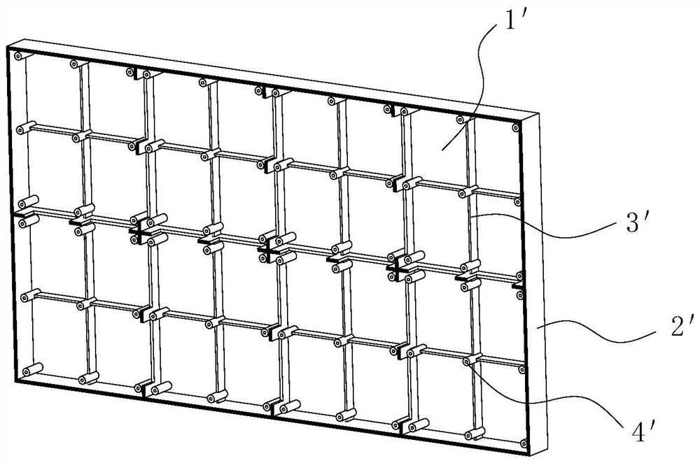
The inventor finds that the prior art has the following defects in the process of implementing the present invention: 1. The box body is produced by die-casting. Wrap the rear mold of the mold, causing the area where the thimble pushes out of the middle of the box to arch backward (that is, to the back of the box) when the mold is released; On the front of the box body, after the die-casting box body is cooled, the tightening force when the main ribs shrink will deform the box body; 3. The box reinforcement ribs 3' are regularly distributed horizontally and vertically, making the four corners of the box body less effective against external force deformation, and easy to Cause warping of the four corners; 4. The back of the box is relatively flat. When the box blank is die-casted, the back is easy to stick to the front mold of the mold, resulting in deformation of the box.

Method used


Image

  • LED cabinet, manufacturing method of LED cabinet and LED display
  • LED cabinet, manufacturing method of LED cabinet and LED display
  • LED cabinet, manufacturing method of LED cabinet and LED display

Examples


Embodiment Construction

[0045] In order to make the technical problems solved by the present invention, the technical solutions adopted and the technical effects achieved clearer, the technical solutions of the embodiments of the present invention will be further described in detail below in conjunction with the accompanying drawings. Obviously, the described embodiments are only the technical solutions of the present invention. Some, but not all, embodiments. Based on the embodiments of the present invention, all other embodiments obtained by those skilled in the art without creative efforts fall within the protection scope of the present invention.

[0046]In the description of the present invention, unless otherwise clearly specified and limited, the terms "connected", "connected" and "fixed" should be understood in a broad sense, for example, it can be a fixed connection, a detachable connection, or an integrated ; It can be a mechanical connection or an electrical connection; it can be a direct ...


PUM


Abstract

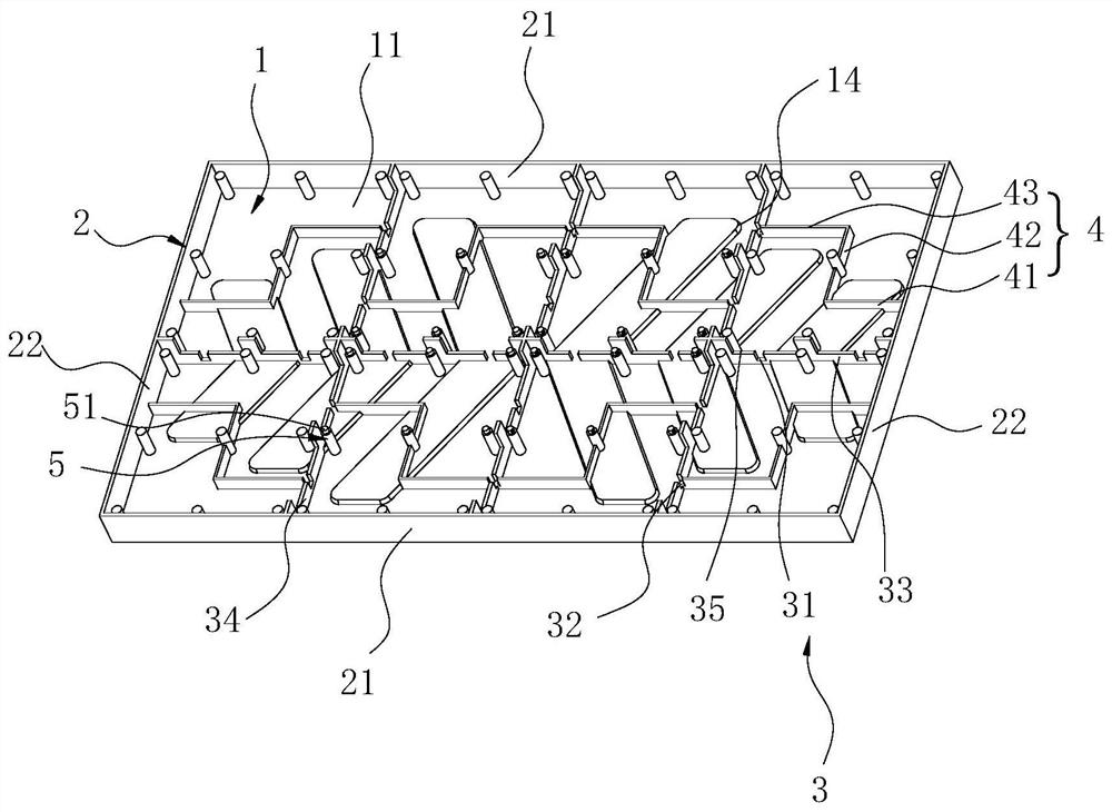
The present invention relates to the technical field of display screens, and in particular to an LED box body, a manufacturing method of the LED box body, and an LED display screen. One side of the wall is the first side, and the first side is provided with main reinforcing ribs criss-crossing, and the main reinforcing ribs are provided with a plurality of first gaps at intervals along its length direction, and the main reinforcing ribs divide the space in the surrounding wall into multiple areas , there is an auxiliary reinforcing rib in the area, at least one end of the auxiliary reinforcing rib is connected with the main reinforcing rib whose length extends along the first direction, and a second notch is provided at the junction of the two, and the first notch and the second notch are both facing away from the body side. By setting the first notch, it is possible to avoid the large tightening force of the main rib during the die-casting cooling process, and by setting the second notch, the stress at the connection between the main rib and the auxiliary rib can be eliminated, thereby effectively avoiding the LED The box is deformed.

Description

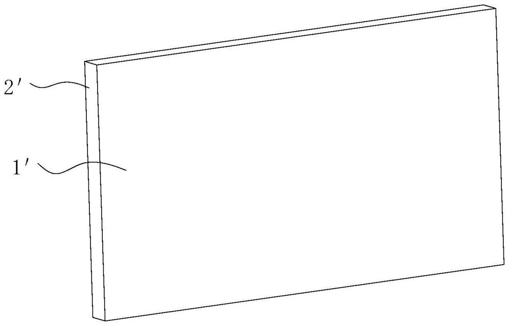
technical field [0001] The invention relates to the technical field of display screens, in particular to an LED box body, a method for manufacturing the LED box body, and an LED display screen. Background technique [0002] The LED display is a flat panel display, which is spliced ​​by small LED module panels. Each LED module panel includes an LED box and a display module. The display module is installed by magnetic attraction or screw fixing. on the LED box. With the improvement of LED display technology, the pixel pitch is getting smaller and smaller, and the requirements for the flatness of the front of the cabinet are getting higher and higher. The structure of the existing LED box is as follows figure 1 and 2 As shown, the box body includes a box body body 1' of a flat structure and a surrounding wall 2' annularly arranged on the front periphery of the box body body 1', and the front side of the box body body 1' is provided with several Regular criss-cross ribs 3', ...

Claims


Application Information

Patent Timeline
Patent Type & Authority Patents(China)
IPC IPC(8): G09F9/33
CPCG09F9/33
Inventor 吴瑞彬
Owner XIAN QINGSONG PHOTOELECTRIC TECH CO LTD
Learn More