Antenna test system, method and device, electronic equipment and storage medium
A test system and antenna technology, applied in diversity/multi-antenna systems, radio transmission systems, transmission systems, etc., can solve the problems of poor test objectivity, long test time, and low test efficiency.
- Summary
- Abstract
- Description
- Claims
- Application Information
AI Technical Summary
Problems solved by technology
Method used
Image

Examples
Embodiment 1
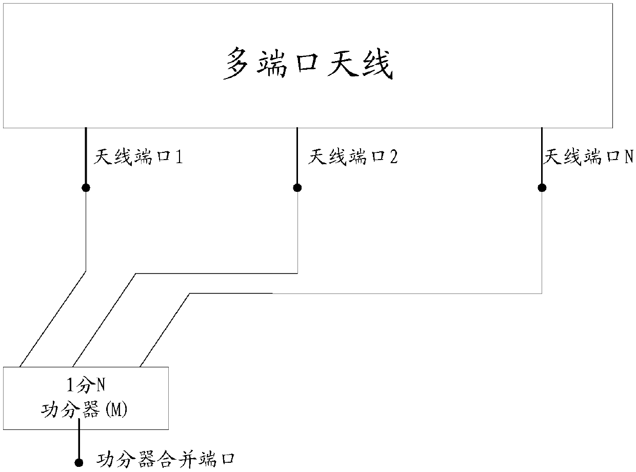
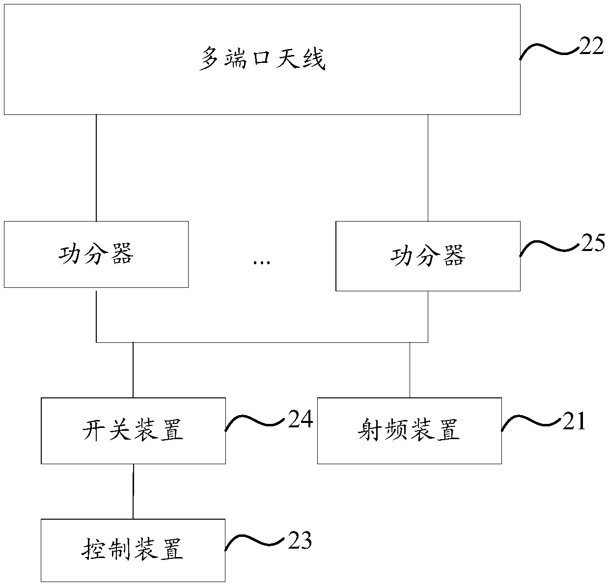
[0047] An embodiment of the present invention provides an antenna test system, including a radio frequency device 21 for outputting radio frequency signals and a multi-port antenna 22 to be tested, such as figure 2As shown, the system also includes: a control device 23 , a switching device 24 and at least two power dividers 25 . Wherein, each power divider 25 is used to simulate different working states of the multi-port antenna 22 to be tested.
[0048] Specifically, such as figure 2 As shown, each power divider 25 is connected to the switch device 24 and the radio frequency device 21 respectively; the control device 23 is connected to the switch device 24, and is used to determine the target power that satisfies the test requirement according to the current test requirement. divider, and control the switch device 24 to connect the target power divider to the multi-port antenna 22 to be tested.
[0049] Since the switch device 24 is respectively connected to each power di...
Embodiment 2
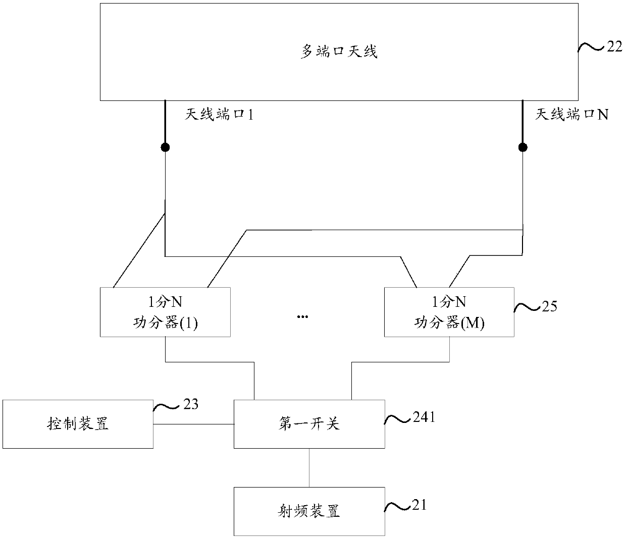
[0052] In order to realize the automatic testing of the different working states of the multi-port antenna 22 to be tested, on the basis of the above-mentioned embodiments, in the embodiment of the present invention, specific methods such as image 3 The antenna test system shown tests multiport antennas.
[0053] Specifically, the switch device 24 includes: a first switch 241, the control end of the first switch 241 is connected to the control device 23, and the first switch end of the first switch 241 is connected to the radio frequency device 21, so Each second switch end of the first switch 241 is connected to a corresponding power divider 25, and each power divider 25 is respectively connected to each antenna port on the multi-port antenna 22 to be tested.
[0054] Since the first switch 241 is connected between the radio frequency device 21 and the power divider 25, and the first switch 241 is provided with a first switch terminal and a plurality of second switch termina...
Embodiment 3
[0062] In order to realize the automatic testing of the different working states of the multi-port antenna 22 to be tested, on the basis of the above-mentioned embodiments, in the embodiment of the present invention, it is also possible to adopt such Figure 4 The antenna test system shown tests multiport antennas.
[0063] Specifically, the switching device 24 also includes: a second switch 242, wherein the number of the second switches 242 is the same as the number of antenna ports on the multi-port antenna 22 to be tested, for each of the second switches 242, the control end of the second switch 242 is connected to the control device 23, the first switch end of the second switch 242 is connected to the corresponding antenna port, and each second switch end of the second switch 242 is connected to the corresponding power divider device 25.
[0064] Since the second switch 242 with the same number of antenna ports on the multiport antenna 22 to be tested is connected between...
PUM
 Abstract
Description
Claims
Application Information
 - R&D
- Intellectual Property
- Life Sciences
- Materials
- Tech Scout
- Unparalleled Data Quality
- Higher Quality Content
- 60% Fewer Hallucinations
Browse by: Latest US Patents, China's latest patents, Technical Efficacy Thesaurus, Application Domain, Technology Topic, Popular Technical Reports.
© 2025 PatSnap. All rights reserved.Legal|Privacy policy|Modern Slavery Act Transparency Statement|Sitemap|About US| Contact US: help@patsnap.com