
Thermal insulation door and window

A thermal insulation, door and window technology, applied in door/window applications, windows/doors, fire doors, etc., can solve the problems of increasing window manufacturing costs, hidden safety hazards, power consumption, etc., and achieves simple structure, convenient processing, and economical low cost effect

Inactive Publication Date: 2020-04-07
上饶市百顺实业有限公司
View PDF6 Cites 1 Cited by
  • Summary
  • Abstract
  • Description
  • Claims
  • Application Information

AI Technical Summary

Problems solved by technology

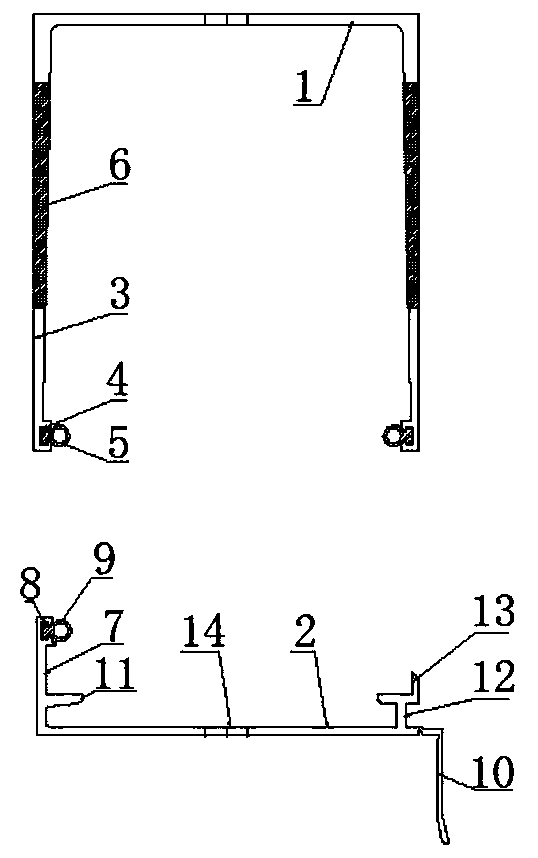
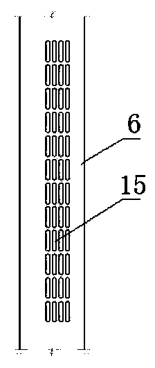
[0002] The existing solution is to increase the size of the side of the window and install ventilation and heat insulation equipment to achieve ventilation and heat insulation. This method greatly increases the manufacturing cost of the window and consumes electricity. There is a great potential safety hazard, and it cannot be well solved to achieve indoor and outdoor natural ventilation and heat insulation under unattended conditions. Currently, the doors and windows on the market need to be closed to achieve ventilation and heat insulation. There is no one that does not affect the waterproof performance. Under the premise of achieving micro ventilation and heat insulation structure, the present invention realizes the communication between indoor and outdoor by setting elongated mesh holes on the upper edge, so as to realize ventilation and heat insulation. The ventilation mesh is located at the top of the whole window

Method used


Image

  • Thermal insulation door and window
  • Thermal insulation door and window

Examples


Embodiment Construction

[0019] The following will clearly and completely describe the technical solutions in the embodiments of the present invention with reference to the accompanying drawings in the embodiments of the present invention. Obviously, the described embodiments are only some, not all, embodiments of the present invention. Based on the embodiments of the present invention, all other embodiments obtained by persons of ordinary skill in the art without making creative efforts belong to the protection scope of the present invention.

[0020] In describing the present invention, it should be understood that the terms "upper", "lower", "front", "rear", "left", "right", "top", "bottom", "inner", " The orientation or positional relationship indicated by "outside", etc. is based on the orientation or positional relationship shown in the drawings, and is only for the convenience of describing the present invention and simplifying the description, rather than indicating or implying that the referre...


PUM


Abstract

The invention relates to the technical field of auxiliary frame edge covering, in particular to a thermal insulation door and window. The thermal insulation door and window comprises an upper component and a lower component. The upper component and the lower component are matched for use. The two ends of the upper component are fixedly connected with upper covered edges. The upper covered edges are symmetrically arranged based on the upper component. The upper covered edges are perpendicular to the upper component. The ends, far away from the upper component, of the upper covered edges arranged symmetrically are provided with sealing grooves. Upper sealing rubber strips are arranged in the upper sealing grooves. The upper covered edges arranged symmetrically further comprise ventilating thermal insulation plates. One end of the lower component is provided with a lower covered edge. The end, far away from the lower component, of the lower covered edge is provided with a lower sealing groove. A lower sealing rubber strip is arranged in the lower sealing groove. The lower covered edge is perpendicular to the lower component. According to the thermal insulation door and window, the upper covered edges are provided with long net holes to realize communication between the indoor and the outdoor, so that the ventilation and thermal insulation effects are achieved. The long ventilationnet holes are located on the top of the whole window. The ventilation and thermal insulation function is achieved through natural force without energy consumption, and the performance of the whole window is not affected.

Description

technical field [0001] The invention relates to the technical field of edge wrapping with a frame, in particular to a door and window capable of heat preservation and heat insulation. Background technique [0002] The existing solution is to increase the size of the side of the window and install ventilation and heat insulation equipment to achieve ventilation and heat insulation. This method greatly increases the manufacturing cost of the window and consumes electricity. There are great potential safety hazards, and it cannot solve the problem of natural ventilation and heat insulation indoors and outdoors when no one is on duty. Currently, the doors and windows on the market need to be closed to achieve ventilation and heat insulation. There is no one that does not affect the waterproof performance. Under the premise of achieving micro-ventilation and heat insulation structure, the present invention realizes the communication between indoor and outdoor by setting elongated...

Claims


Application Information

Patent Timeline
IPC IPC(8): E06B1/02E06B7/14E06B7/22E06B7/10E06B5/16
CPCE06B1/02E06B5/161E06B5/164E06B5/168E06B7/10E06B7/14E06B7/22
Inventor 孙光明
Owner 上饶市百顺实业有限公司
Learn More