
Motor iron core structure

A technology of iron core structure and core body, applied in the direction of magnetic circuit shape/style/structure, electrical components, electromechanical devices, etc., can solve the problems of falling off, high friction force of inserts, and insufficient inserts.

Inactive Publication Date: 2020-04-03
永昌控股集团有限公司
View PDF8 Cites 0 Cited by
  • Summary
  • Abstract
  • Description
  • Claims
  • Application Information

AI Technical Summary

Problems solved by technology

The latter has better assembly difficulty and manufacturability, but there are corresponding problems in the insert structure
If there is an interference fit between the insert and the groove, the friction force will be large when the insert is assembled. If the insert and the groove are not an interference fit, the insert will not be strong enough and there is a risk of falling off under vibration conditions

Method used


Image

  • Motor iron core structure
  • Motor iron core structure
  • Motor iron core structure

Examples


Embodiment

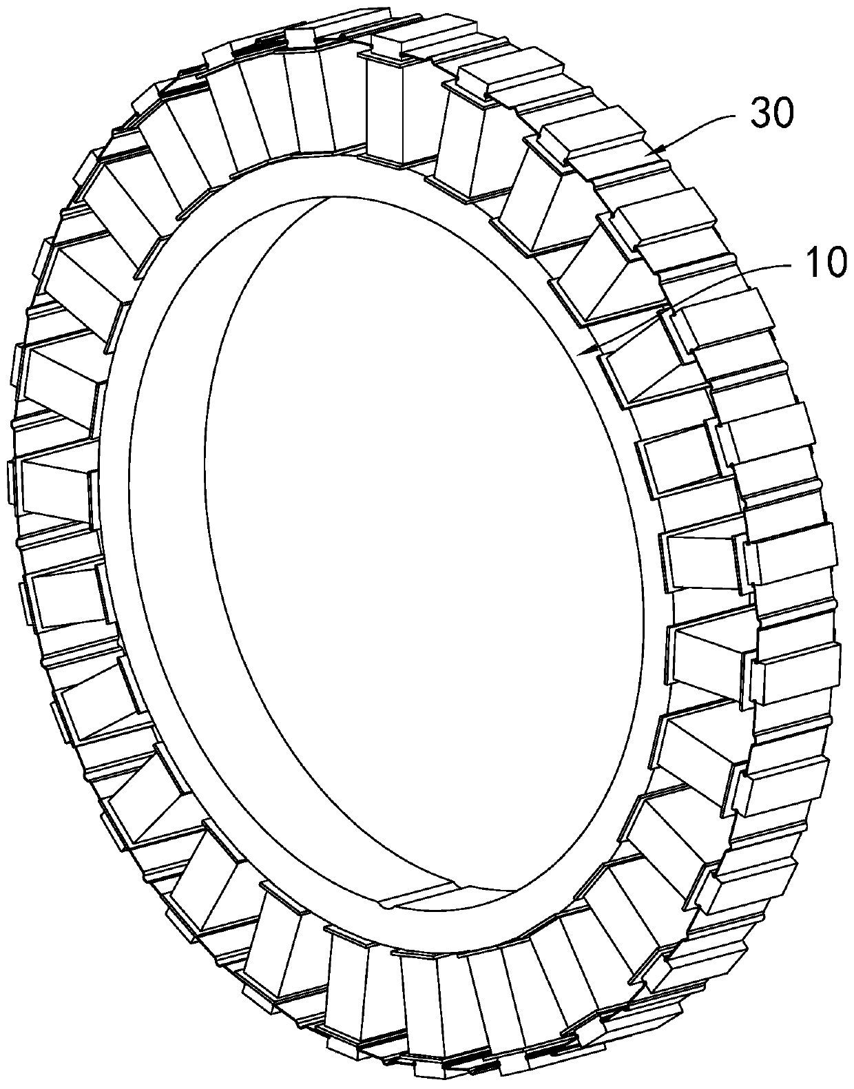
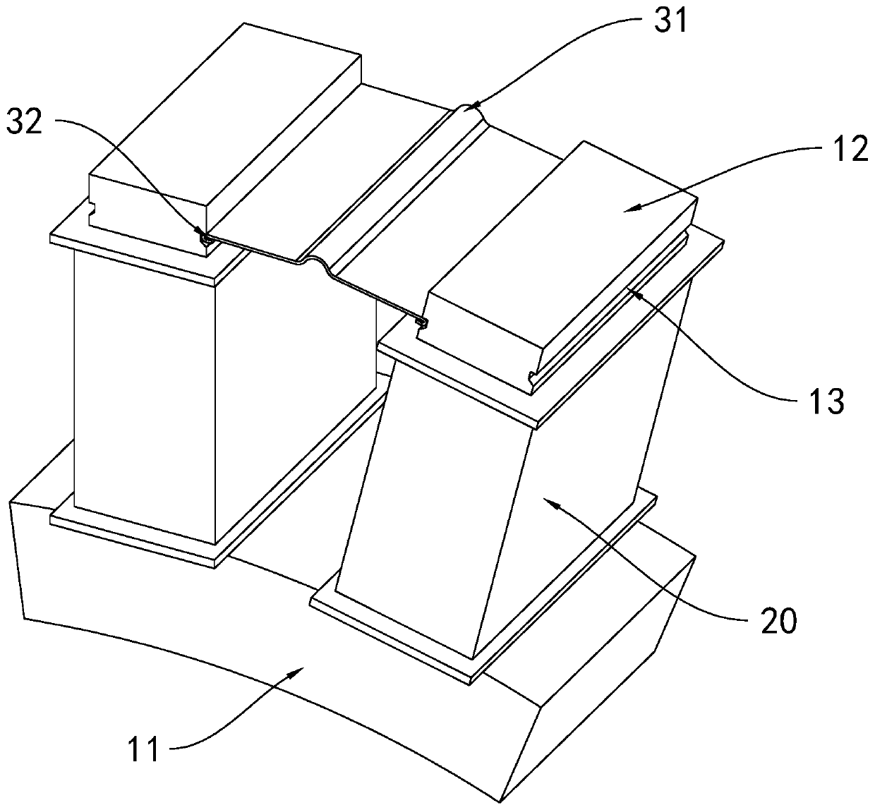
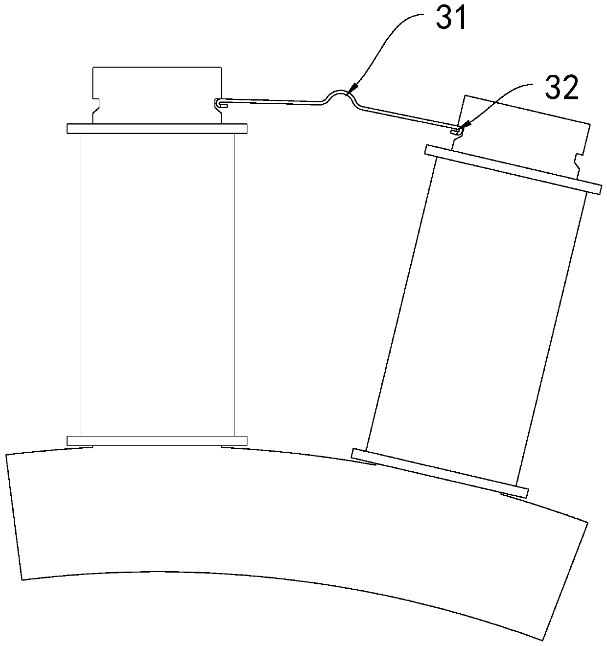
[0019] Embodiment: A motor core structure, including a core body 10, the core body 10 includes a ring-shaped yoke part 11, and teeth parts 12 are distributed around the outside of the yoke part 11. The tooth part 12 is a cuboid structure, the tooth part 12 is radially covered with an insulating case 20 , and a winding wire is wound around the insulating case 20 . It also includes an insertion piece 30 for limiting the radial position of the insulating case 20 , and an axial groove 13 is provided on the side of the tooth portion 12 , and the groove 13 is matched with the insertion piece 30 .

[0020] An elastic portion 31 is disposed in the middle of the insertion piece 30 , and the width of the insertion piece 30 is changed through deformation of the elastic portion 31 . Specifically, the radial section of the elastic portion 31 is arc-shaped. The edge matching the groove 13 on the insertion piece 30 is provided with a curling portion 32, and the two ends of the curling porti...


PUM


Abstract

The invention discloses a motor iron core structure. The motor iron core structure comprises a core body (10), the core body (10) comprises annular yoke parts (11), and tooth parts (12) are annularlydistributed outside the yoke parts (11); the tooth parts (12) are of a cuboid structure, the tooth parts (12) sleeves insulating shells (20) in the radial direction, and winding wires are wound aroundthe insulating shells (20). Insertion pieces (30) are used for limiting the radial positions of the insulating shells (20), axial grooves (13) are formed in the side faces of the tooth parts (12), and the grooves (13) are matched with the insertion pieces (30). The motor iron core structure has the characteristics of being easy to assemble and good in stability.

Description

technical field [0001] The invention relates to a large washing machine motor iron core, in particular to an independent winding type motor iron core. Background technique [0002] Some washing machine motors have the structure of inner stator and outer rotor. Among them, the rotor is similar to a disc structure, and the magnets are distributed on the inner ring wall of the disc, and the stator includes a ring-shaped iron core body, and the teeth are distributed in a ring shape outside the iron core, and the teeth have umbrella-shaped tops, and the teeth are wound with windings through an insulating structure. Wire. The iron core of the conventional structure often adopts manual embedding, which leads to high work intensity, low efficiency, and easy to cause quality problems. Therefore, the automatic embedded wire stator core came into being. The iron core of this structure is mainly divided into two forms. One is to divide the iron core body into several sectors, and eac...

Claims


Application Information

Patent Timeline
IPC IPC(8): H02K1/18
CPCH02K1/187
Inventor 孙豪远江林飞汪旭亮
Owner 永昌控股集团有限公司
Learn More