
Electromagnetic relay deicing system

An electromagnetic relay and elimination system technology, applied in the direction of electromagnetic relay, electromagnetic relay details, relay, etc., can solve the problems that metal cannot be contacted, cannot be electrically conducted, cannot supply power or send signals through electromagnetic relay, etc., to achieve elimination Effect of icing and suppressing energy loss

Pending Publication Date: 2020-04-03
SUBARU CORP
View PDF1 Cites 4 Cited by
  • Summary
  • Abstract
  • Description
  • Claims
  • Application Information

AI Technical Summary

Problems solved by technology

[0007] In addition, if ice particles or the like are formed on the surface of the contact point, the ice will hinder the contact between the metals and the electrical conduction will not be possible. Therefore, operations such as power supply or signal transmission through the electromagnetic relay cannot be performed.

Method used


Image

  • Electromagnetic relay deicing system
  • Electromagnetic relay deicing system
  • Electromagnetic relay deicing system

Examples


no. 1 approach

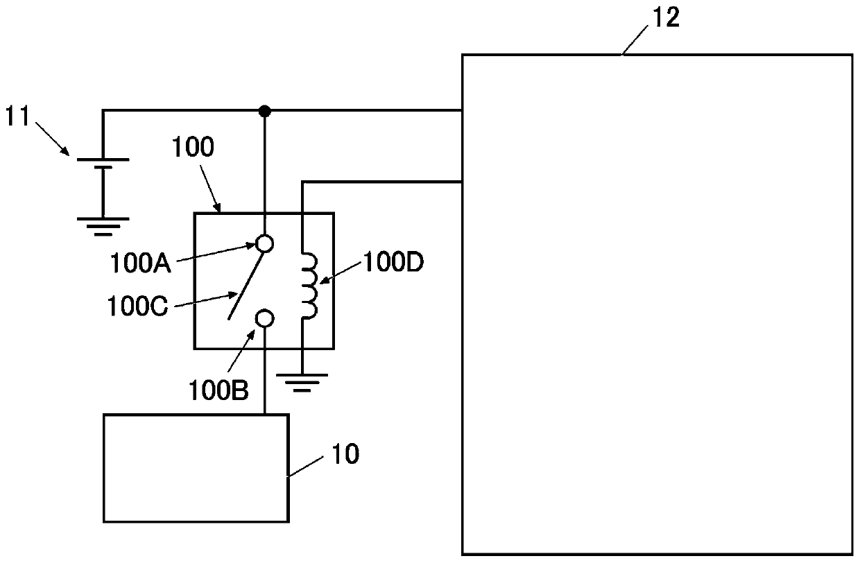
[0068] For example, in electric vehicles, such as figure 1 As shown, there are cases where drive system components 10 such as an inverter are connected to auxiliary battery 11 via electromagnetic relay 100, and power is supplied from auxiliary battery 11 to drive system components 10 via electromagnetic relay 100 when the electric vehicle is started. The drive system component 10 is started.

[0069] It should be noted that after the drive system unit 10 is activated, the power supply mechanism for supplying power to the drive system unit 10 is switched from the auxiliary battery 11 to a main battery not shown or the like.

[0070] Such as figure 1 As shown, in this case, the electromagnetic relay 100 is composed of a common terminal (COM terminal) 100A, a normally open terminal 100B, a movable piece 100C, an exciting coil 100D, and the like.

[0071] Furthermore, the common terminal 100A is connected to the auxiliary battery 11 , and the normally-open terminal 100B is conne...

no. 2 approach

[0117] In addition, conventionally, there are cases where reserve (standby) wiring and the like are provided in the control circuit.

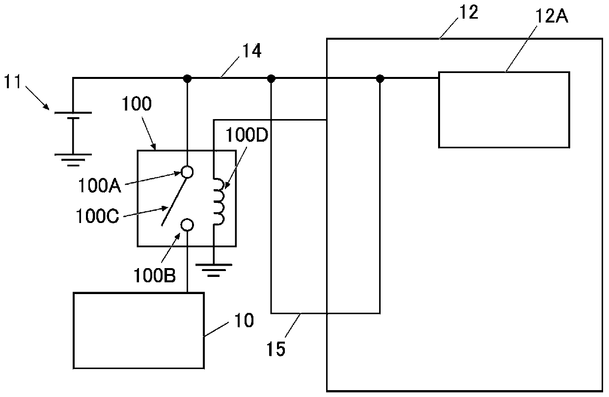
[0118] in e.g. figure 1 In the control system shown, such as image 3 As shown, there is a case where a storage wiring 15 is provided for the main wiring 14 connecting the auxiliary battery 11 and / or the main battery (not shown) and the internal circuit 12A of the control circuit 12 .

[0119] Therefore, the electromagnetic relay deicing system 2 can be configured using the wiring 15 for storage. Hereinafter, it demonstrates concretely.

[0120] In addition, below, the same code|symbol as the case of 1st Embodiment is attached|subjected to the member etc. which are the same as 1st Embodiment, and is shown. In addition, explanations may be omitted for the same members and the like as those of the first embodiment.

[0121] Figure 4 It is a figure which shows the structure of the electromagnetic relay deicing system 2 of this embodiment.

...


PUM


Abstract

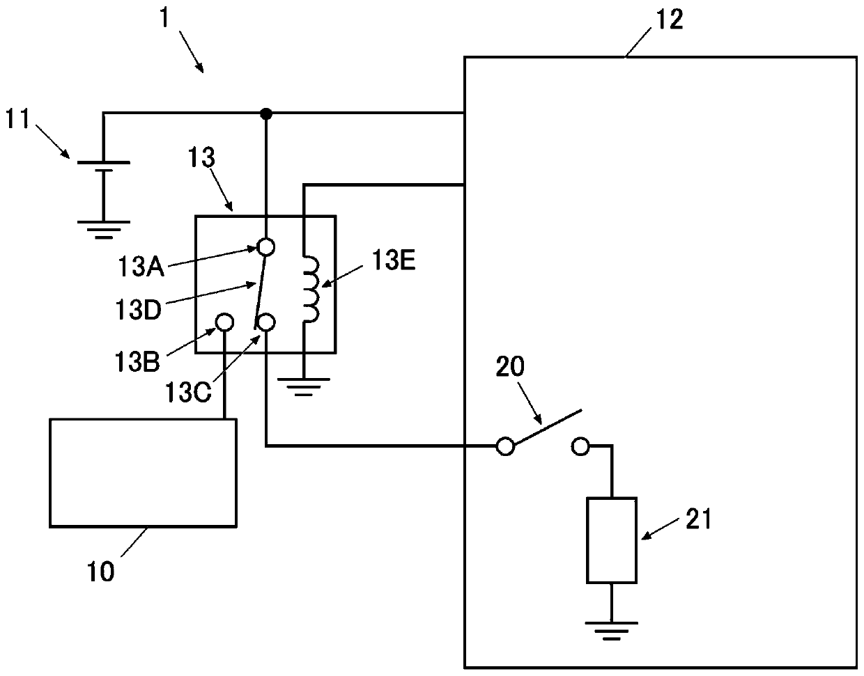
The invention provides an electromagnetic relay deicing system which can suppress energy loss without increasing the on and off times of the electromagnetic relay and can reliably eliminate the icingof the electromagnetic relay without installation of a large-scale device or circuit. The electromagnetic relay deicing system 1 includes an electromagnetic relay 13 that includes a common terminal 13A, a normally open terminal 13B, and a normally closed terminal 13C and that supplies electric power from an electric power supplier 11 to an electrical apparatus 10 when the common terminal 13A and the normally open terminal 13B are connected, and a control circuit 12 that controls an on-state and an off-state of the electromagnetic relay. During the on-state of the electromagnetic relay, the common terminal 13A and the normally open terminal 13C are connected by a movable piece 13D. During the off-state of the electromagnetic relay, the common terminal and the normally closed terminal are connected by the movable piece. The control circuit deices the electromagnetic relay by causing, during the off-state of the electromagnetic relay, electric conduction between the common terminal and the normally closed terminal connected by the movable piece so that ice on a surface of the normally open terminal melts.

Description

technical field [0001] The present invention relates to an electromagnetic relay deicing system, and more particularly to a system for deicing an electromagnetic relay that controls power supply to motor equipment and the like. Background technique [0002] For example, in vehicles such as automobiles, an electromagnetic relay of the type (two-contact relay) that mechanically connects or disconnects the movable piece to the terminal is widely used, or the connection object of the movable piece is connected between the two terminals. Switch between electromagnetic relays of the type (3-contact relay). [0003] In addition, the electromagnetic relay supplies power to various electronic control units (ECUs) and / or drivers, or sends start signals, etc., to support the basic functions of the vehicle such as starting, running, turning, and stopping the vehicle. [0004] Therefore, if the electromagnetic relay freezes, these functions cannot be realized and serious problems arise....

Claims


Application Information

Patent Timeline
Patent Type & Authority Applications(China)
IPC IPC(8): H01H47/00
CPCH01H47/00H01H50/12H01H45/12H01H2047/025H01H47/02H01R2201/26H01R13/629
Inventor 加藤大介
Owner SUBARU CORP
Learn More