Connecting device for pipeline and aerator

A connecting device and aerator technology, which is applied in water aeration, sleeve/socket connection, pipe/pipe joint/pipe fitting, etc., can solve the problems of high mold opening cost, connection failure, time-consuming and labor-consuming plastic glue, etc. problems, achieve low installation and time costs, reduce the number of molds, and reduce development costs

Pending Publication Date: 2020-04-03
江苏环川环境工程有限公司
View PDF0 Cites 0 Cited by
  • Summary
  • Abstract
  • Description
  • Claims
  • Application Information

AI Technical Summary

Problems solved by technology

[0005] 1. Plastic gluing is time-consuming and labor-intensive, and it is prone to air leakage caused by uneven gluing. At the same time, the glue is corroded by sewage in sewage, and there is a risk of glue opening and product falling off;
[0006] 2. Although the rubber knock-in nozzle avoids the risk of air leakage and nozzle falling off, during the installation process, the nozzle will rotate as the product is tightened, which makes installation troublesome and inefficient
[0008] 1. The cost is too high;
[0009] 2. Stainless steel bolts are severely corroded in the sewage with high chloride ions, resulting in connection failure;
[0010] 3. Stainless steel bolts are complex, time-consuming, inconvenient, and inefficient during processing, assembly, transportation, and on-site installation
[0012] 1. More components are required, and the mold opening cost is high;
[0013] 2. It is easy to loosen during thermal expansion and contraction and working vibration;
[0014] 3. Poor installation convenience

Method used


Image

  • Connecting device for pipeline and aerator
  • Connecting device for pipeline and aerator
  • Connecting device for pipeline and aerator

Examples


Embodiment Construction

[0034] In order to describe the technical content, structural features, goals and effects of the present invention in detail, the following examples are given to describe the embodiments in conjunction with the accompanying drawings.

[0035] In describing the present invention, it is to be understood that the terms "central", "longitudinal", "transverse", "front", "rear", "left", "right", "vertical", "horizontal", The orientations or positional relationships indicated by "top", "bottom", "inner", "outer", etc. are based on the orientations or positional relationships shown in the drawings, and are only for the convenience of describing the present invention and simplifying the description, rather than indicating or implying The devices or elements referred to must have a specific orientation, be constructed and operate in a specific orientation, and therefore should not be construed as limiting the scope of the invention.

[0036] The present invention provides a connection d...


PUM


Abstract

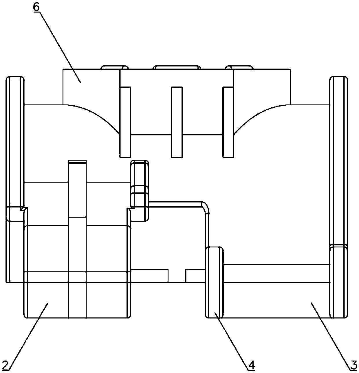
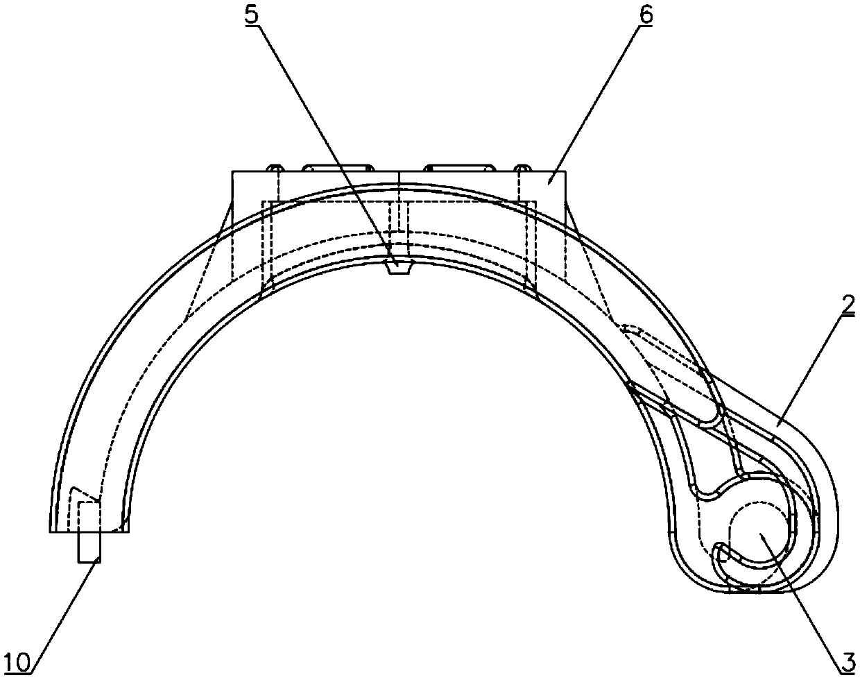
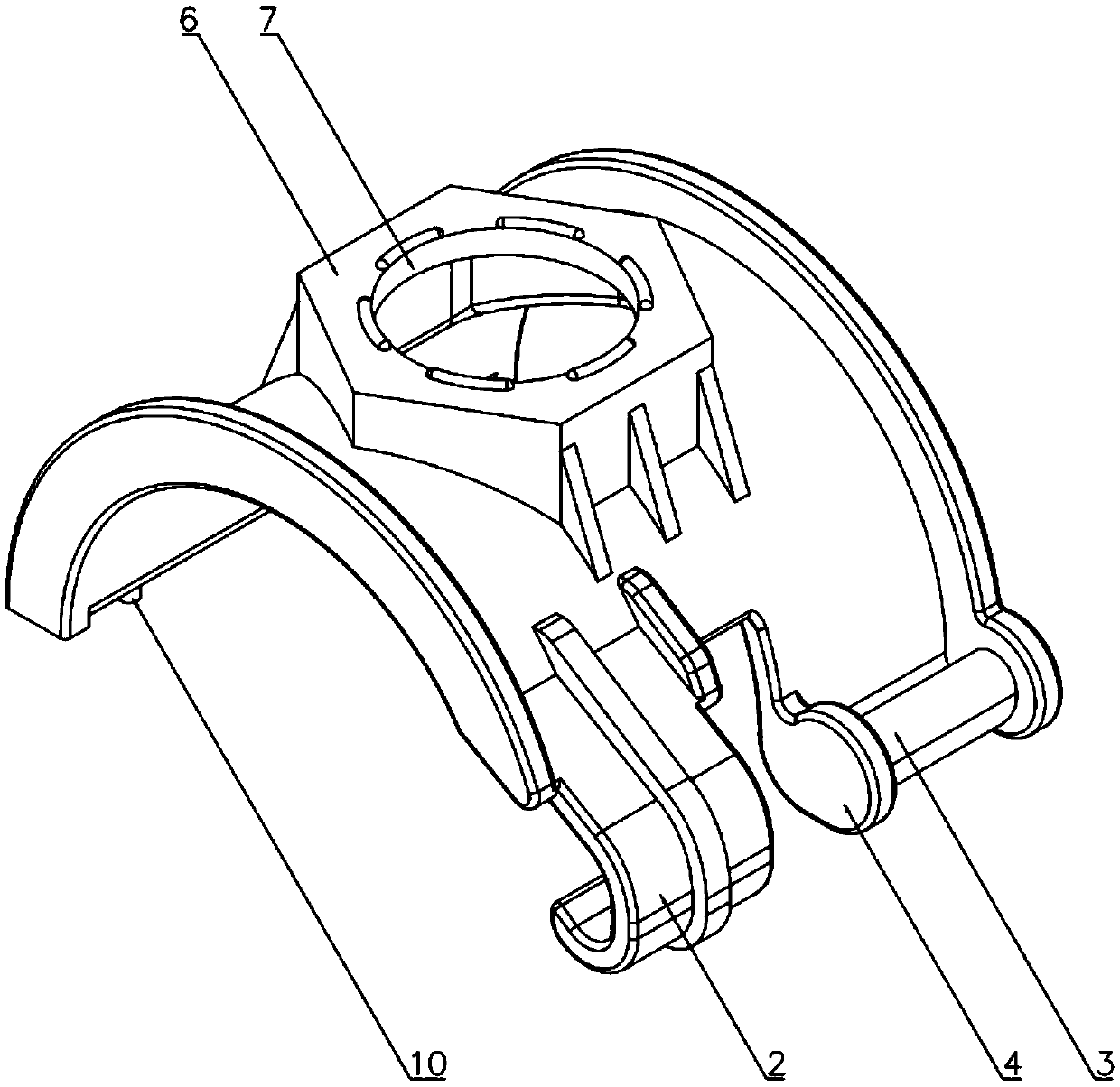
The invention provides a connecting device for a pipeline and an aerator, which comprises two semi-arc-shaped hoops of the completely same structure. A clamping jaw and a positioning rod are arrangedon the left side and the right side of one end of each hoop respectively; the axis of the inner arc face of the clamping jaw coincides with the axis of the positioning rod, the clamping jaw of one hoop is connected with the positioning rod of the other hoop in a clamped mode, and positioning shoulders are arranged at the two ends of the positioning rod of the hoop. A positioning block clamped withthe positioning groove of the pipeline is arranged on the inner arc surface of the hoop; a hexagonal locking block matched with the connecting surface of the aerator is arranged on the outer arc surface of the hoop; the locking block is provided with a through hole, a first connecting block which is provided with an internal thread and is in threaded connection with the external thread of the disc aerator is inserted into the through hole in one hoop, and a second connecting block which is provided with an external thread and is in threaded connection with the internal thread of the tubular aerator is inserted into the through hole in the other hoop; and clamping blocks and connecting grooves for fixing the two hoops are arranged at the ends, away from the clamping jaws, of the hoops. Themanufacturing cost and the mounting cost are low.

Description

technical field [0001] The invention relates to the technical field of an aerator and its accessories, in particular to a connection device between a pipeline and an aerator. Background technique [0002] In the field of sewage treatment, the aerator has a great influence on the oxygen transfer efficiency and the operating cost of sewage treatment. The domestic development and application of aerators began in the mid-1980s, and the representative ones are: perforated tube aerators, corundum aerators, disc microporous aerators, tube aerators, jet aerators, Diffuse aerator, cyclone aerator, etc. [0003] The aerator usually needs to be installed on the pipeline. The connection devices between the aerator and the pipeline in the prior art can be divided into three types, but each has its own shortcomings: [0004] 1. Plastic adhesive type, rubber knock-in type internal and external thread small saddle nozzle: [0005] 1. Plastic gluing is time-consuming and labor-intensive, ...

Claims


Application Information

Patent Timeline
IPC IPC(8): F16L21/06F16L41/12C02F7/00
CPCC02F7/00F16L21/065F16L41/12Y02W10/10
Inventor 征晓勇
Owner 江苏环川环境工程有限公司
Why Eureka
Try Eureka