Ultrasonic pile detection testing device enabling transducers to be synchronously moved at equal distance

A synchronous testing and transducer technology, applied in the testing of infrastructure, construction, infrastructure engineering, etc., can solve the problems of reducing detection efficiency, prolonging operation time, inconsistent signal line length, etc., to improve detection efficiency and improve accuracy degree of effect

Pending Publication Date: 2020-04-03
CHINA STATE CONSTR PORT ENG GRP
View PDF0 Cites 1 Cited by
  • Summary
  • Abstract
  • Description
  • Claims
  • Application Information

AI Technical Summary

Problems solved by technology

However, in the actual operation process, since the signal lines of each transducer are independently inserted into the acoustic tube, the retractable devices of the two signal lines are independent of each other, which usually makes the length of the signal lines in the two acoustic tubes inconsistent. , has an impact on the detection waveform, and needs to be manually searched for scale alignment to achieve unity, thereby prolonging the operation time and reducing the detection efficiency

Method used


Image

  • Ultrasonic pile detection testing device enabling transducers to be synchronously moved at equal distance
  • Ultrasonic pile detection testing device enabling transducers to be synchronously moved at equal distance
  • Ultrasonic pile detection testing device enabling transducers to be synchronously moved at equal distance

Examples


Embodiment 1

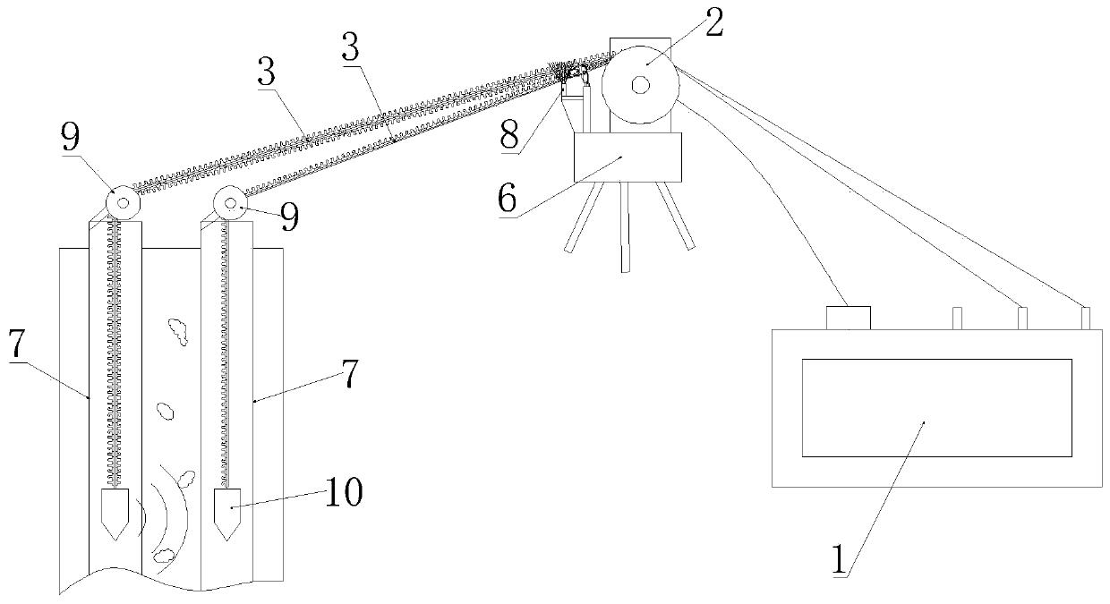
[0024] An equidistant synchronous testing device for ultrasonic pile measuring transducers, comprising an ultrasonic detector 1, a pulley 2 and a signal line 3, the signal line 3 is wound on the pulley 2, and a transducer 10 is installed at its end, The signal wires 3 are a pair, and the two signal wires 3 are fixedly connected through the engaging part 4, the engaging part 4 can be opened and fastened, and the buckle 5 is installed on the engaging part 4, The buckle 5 can control the fastening of the engaging portion 4 .

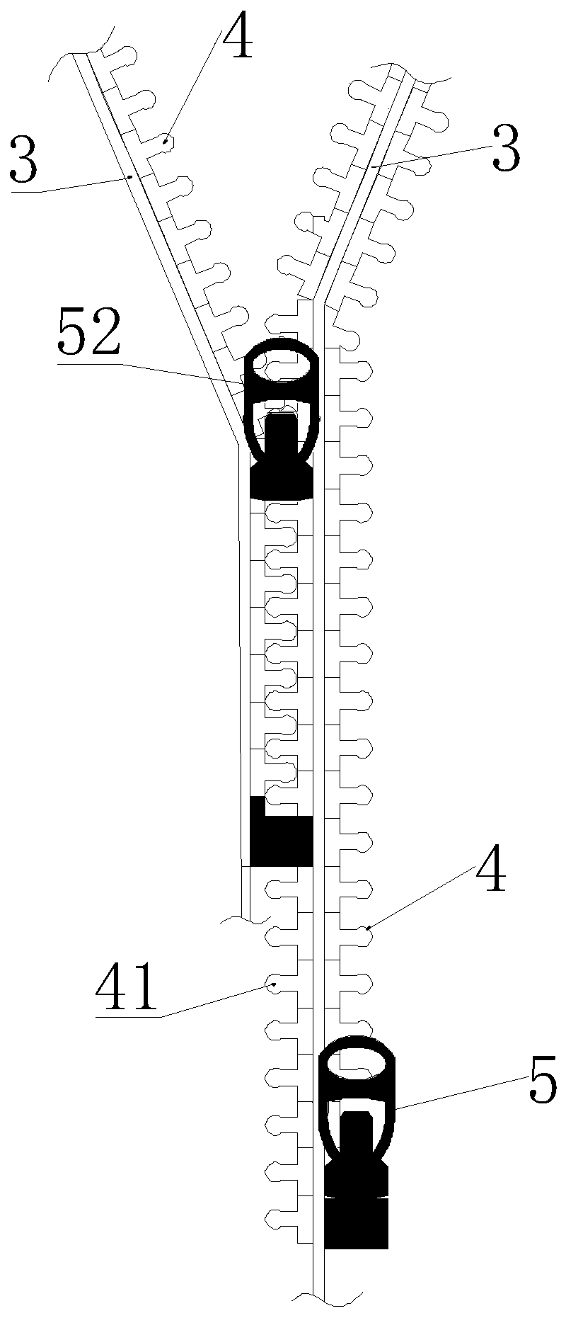
[0025] Wherein, the engaging part 4 is a zipper, and the two chains of the zipper are respectively fixed on the two signal lines 3, and the buckle 5 is a sliding part 1 on the zipper, and the sliding part 1 is a zipper, The zipper part between the zipper one and the transducer 10 is in an open state. Both the pulley 2 and the buckle 5 are installed on the tripod 6 , and the buckle 5 is located on the side where the end of the signal line 3 protrudes. Afte...

Embodiment 2

[0029] An equidistant synchronous testing device for ultrasonic pile measuring transducers, comprising an ultrasonic detector 1, a pulley 2 and a signal line 3, the signal line 3 is wound on the pulley 2, and a transducer 10 is installed at its end, The signal wires 3 are a pair, and the two signal wires 3 are fixedly connected through the engaging part 4, the engaging part 4 can be opened and fastened, and the buckle 5 is installed on the engaging part 4, The buckle 5 can control the fastening of the engaging portion 4 .

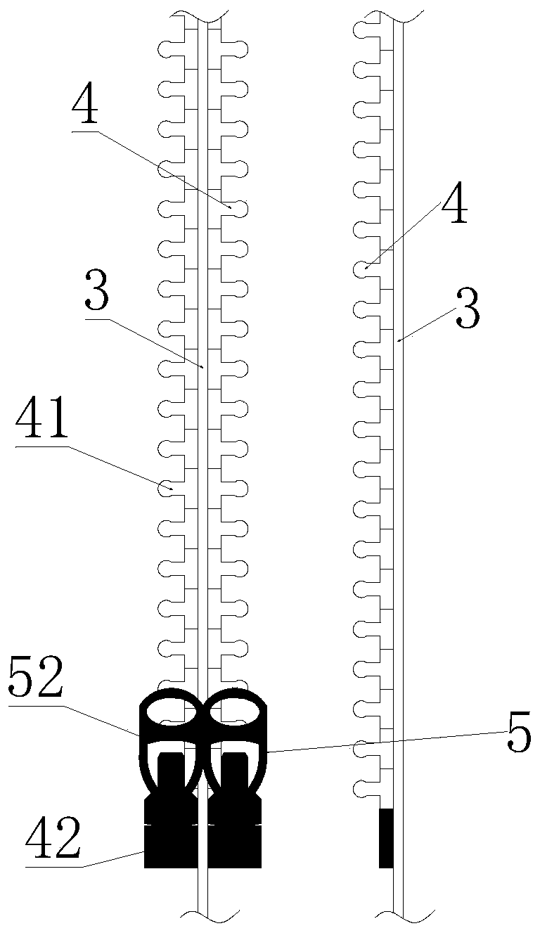
[0030] Wherein, the engaging portion 4 includes a plurality of evenly distributed paired protrusions 41 and grooves 42 , and the protrusions 41 are inserted into the grooves 42 to fasten and fix the two signal lines 3 to each other. The buckle 5 is a cylindrical structure set on the two signal lines 3 , and the width of the inner cylinder of the buckle 5 is the widest width of the two signal lines 3 after the protrusion 41 and the groove 42 are fastened tog...


PUM


Abstract

The invention relates to the technical field of cast-in-place pile detection, in particular to an ultrasonic pile detection testing device enabling transducers to be synchronously moved at equal distance. The ultrasonic pile detection testing device enabling the transducers to be synchronously moved at equal distance comprises an ultrasonic detecting instrument, a pulley device and a pair of signal lines. The signal liens are coiled on the pulley device. The tail ends of the signal lines are provided with the transducers. The two signal lines are fixedly connected through a clamping portion. The clamping portion can be opened and buckled. A buckle is installed on the clamping portion. The buckle can control buckling of the clamping portion. By the adoption of the ultrasonic pile detectiontesting device enabling the transducers to be synchronously moved at equal distance, the transducers are synchronously moved at equal distance, so that the operation time is shortened, the work efficiency is improved, and detection errors are lowered.

Description

technical field [0001] The invention relates to the technical field of cast-in-situ pile detection, in particular to an equidistant synchronous testing device for ultrasonic pile measuring transducers. Background technique [0002] In the process of pile foundation ultrasonic detection, in order to ensure the accuracy of detection, the receiving and transmitting transducers should move synchronously at the same height or at a certain height difference. However, in the actual operation process, since the signal lines of each transducer are independently inserted into the acoustic tube, the retractable devices of the two signal lines are independent of each other, which usually makes the length of the signal lines in the two acoustic tubes inconsistent. , which affects the detection waveform, it is necessary to manually search for scale alignment to achieve unity, thereby prolonging the operation time and reducing the detection efficiency. Contents of the invention [0003]...

Claims


Application Information

Patent Timeline
Patent Type & Authority Applications(China)
IPC IPC(8): E02D33/00
CPCE02D33/00
Inventor 张磊王军盖梅香何长龙王桂敏刘勇华姜乐
Owner CHINA STATE CONSTR PORT ENG GRP
Why Eureka
Try Eureka