Hardware electroplating equipment capable of preventing hole marks

A technology for electroplating equipment and hardware, applied in the electrolysis process, electrolysis components, etc., can solve the problems of impeding the normal passage of current, blockage of electrolysis impurities, and imperfect technical considerations, and achieve the effect of improving processing quality and quality.

Inactive Publication Date: 2020-04-03
戴宗强
View PDF2 Cites 1 Cited by
  • Summary
  • Abstract
  • Description
  • Claims
  • Application Information

AI Technical Summary

Problems solved by technology

[0002] Hardware has become an indispensable part of daily household equipment. In order to improve the wear resistance, conductivity, light reflection, corrosion resistance and aesthetics of hardware, after the traditional hardware processing, it is necessary to use electroplating equipment to make the surface of the workpiece Attach a layer of metal film to prevent metal oxidation, but the current technical considerations are not perfect, and has the following disadvantages: due to the small size of the hardware, it is processed by barrel plating. The barrel wall of the drum is evenly distributed with holes of the same size. As the electroplating drum rotates in a certain direction, the electroplating solution enters the electroplating drum through the holes to generate electroplating reaction. As the electroplating drum is used for a long time, electrolytic dirt is easy to accumulate in the holes and cause blockage. , and then some of the holes in the drum are blocked to prevent the normal passage of current, so that the current density on the surface of the hardware near the normal holes is too high, resulting in holes and reducing the quality of electroplating processing

Method used


Image

  • Hardware electroplating equipment capable of preventing hole marks
  • Hardware electroplating equipment capable of preventing hole marks
  • Hardware electroplating equipment capable of preventing hole marks

Examples


Embodiment

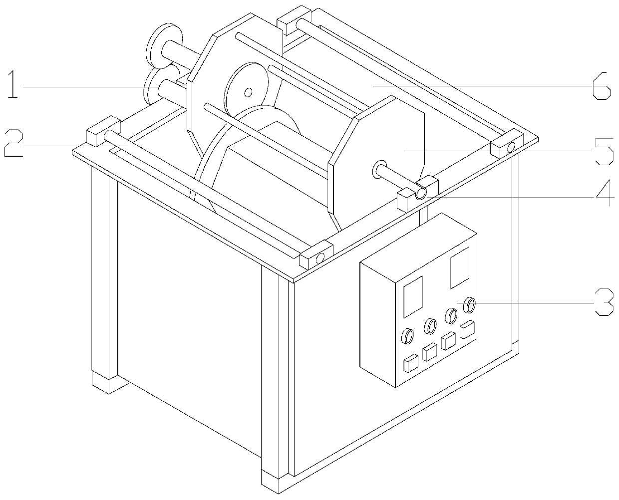
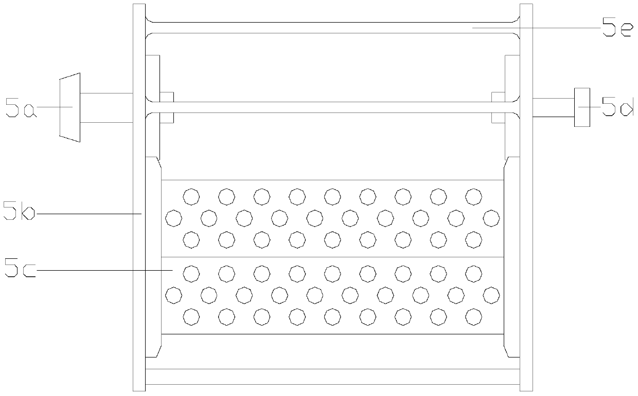
[0024] See Figure 1-Figure 2 , The present invention provides a hardware electroplating equipment for preventing eye marks. Its structure includes a motor drive wheel 1, an anode rod 2, a power control box 3, a cathode conductive device 4, an electroplating drum body 5, and a barrel mounting frame 6. The barrel mounting frame 6 is a hollow rectangular structure without a roof. The anode rods 2 are located at the front and rear ends of the upper surface of the barrel mounting frame 6 and are fixed with the barrel mounting frame 6 by bolts. The power control box 3 is located in the barrel. The right side of the body mounting frame 6 is electrically connected to the electroplating drum body 5. The motor transmission wheel 1 is nested on the left side of the cylinder body mounting frame 6 and is engaged with the electroplating drum body 5, and the cathode conductive device 4 is connected to the cylinder body mounting frame. 6 The upper surface is close together in the middle, the e...


PUM


Abstract

The invention discloses hardware electroplating equipment capable of preventing hole marks. The hardware electroplating equipment structurally comprises a motor transmission wheel, an anode rod, a power control box, a cathode conductive device, an electroplating roller body and a roller body mounting frame, wherein the roller body mounting frame is of a rectangular structure, the anode rod and theroller body mounting frame are fixed together through bolts, and the power control box is located on the right side of the roller body mounting frame. The hardware electroplating equipment is provided with an automatic dirt removing structure, when an electroplating roller tank rotates to the highest position, the automatic dirt removing structure slides leftwards, opens towards the upper end andthe lower end at the same time and penetrates through electroplating holes, electrolytic dirt deposited in the electroplating holes is effectively removed, the situation that holes are formed in thesurface of hardware after electroplating due to uneven current density caused by blockage of part of the holes is avoided, and the machining quality of hardware coating is effectively improved.

Description

Technical field [0001] The invention relates to the field of hardware electroplating equipment, in particular, to a hardware electroplating equipment that prevents hole marks. Background technique [0002] Hardware has become an indispensable part of daily household equipment. In order to improve the wear resistance, conductivity, light reflection, corrosion resistance and beauty of the hardware, the traditional hardware needs to use electroplating equipment to make the surface of the workpiece. A layer of metal film is attached to prevent metal oxidation, but the current technical considerations are not perfect. It has the following shortcomings: due to the small size of the hardware, the barrel plating process is used for processing, and the hardware is placed inside the electroplating drum during work. The barrel wall of the drum is evenly distributed with holes of the same size. As the electroplating drum rotates in a certain direction, the electroplating solution enters the ...

Claims


Application Information

Patent Timeline
Patent Type & Authority Applications(China)
IPC IPC(8): C25D17/20C25D17/00
CPCC25D17/00C25D17/20
Inventor 戴宗强
Owner 戴宗强
Why Eureka
Try Eureka