
Automatic dust falling system and method for coal unloading point of elevator shaft

A well-lifting, automatic technology, applied in the petroleum industry, gas fuel, fuel and other directions, can solve the problems of difficult to meet occupational health requirements, easy to deteriorate coal quality, and increase system safety hazards.

Active Publication Date: 2020-04-03
徐州宇晟安全环保科技有限公司 +1
View PDF13 Cites 4 Cited by
  • Summary
  • Abstract
  • Description
  • Claims
  • Application Information

AI Technical Summary

Problems solved by technology

After on-site practice, it was found that this dust removal method has the following deficiencies: (1) the dust removal rate is low, especially for respirable dust purification efficiency is extremely low (<50%), and it is difficult to meet occupational health requirements; (2) the dust removal The method consumes a lot of water, which is easy to deteriorate the quality of coal, and it is easy to cause corrosion of the hoisting device of the main shaft, which increases the potential safety hazards of the system; (3) In winter, the spraying water pipe is easy to freeze, and the sprayed and leaked accumulated water is easy to cause the ground to freeze. Restricted; (4) The dust emission concentration at the shaft tower cannot meet the national requirements for dust control in coal enterprises

Method used


Image

  • Automatic dust falling system and method for coal unloading point of elevator shaft
  • Automatic dust falling system and method for coal unloading point of elevator shaft
  • Automatic dust falling system and method for coal unloading point of elevator shaft

Examples


Embodiment Construction

[0038] The present invention will be further described below in conjunction with accompanying drawing.

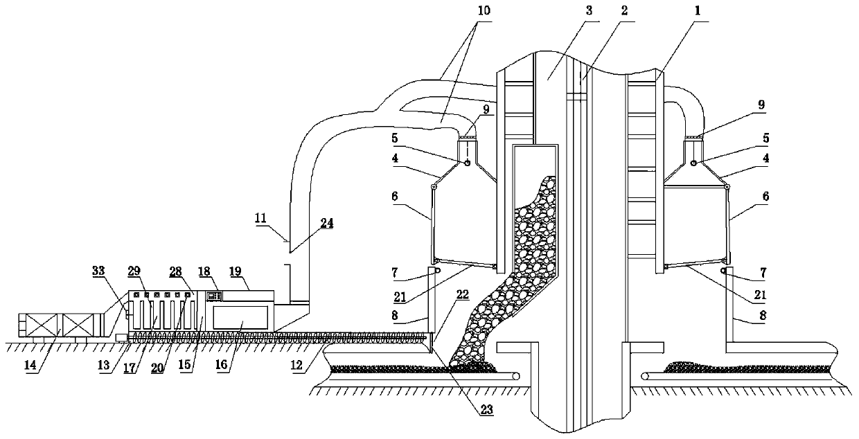
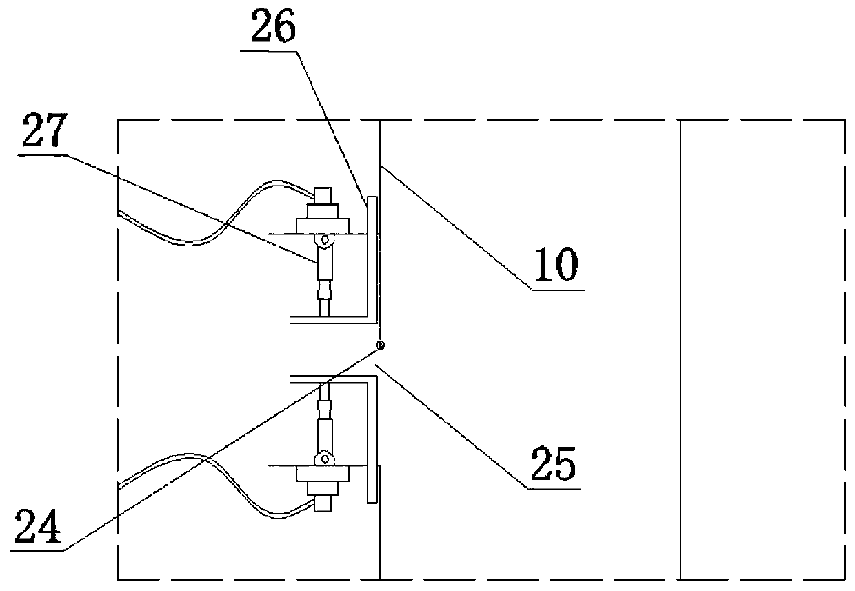
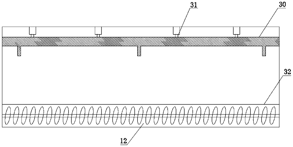
[0039] Such as Figure 1 to Figure 5 As shown, an automatic dust reduction system at the coal unloading point of the lifting shaft includes an axial flow fan 14 arranged outside the lifting shaft 3, a dry dust collector 15, two dust collecting mechanisms, a screw conveyor 12 and a controller 18; The air inlet of the axial flow fan 4 is connected to the air outlet of the dry dust collector 15; two dust collection mechanisms are respectively arranged on the left and right sides of the lifting shaft 3; wherein, the lifting shaft 3 is provided with a lifting rope 2 for lifting;

[0040] The dust collection mechanism includes a dust collection cover 4, a transparent dust shield 6, a hydraulic support A21, a control damper 9, a dust concentration sensor 7 and a gas concentration sensor 5; Between the shaft support frame 1 and the side wall 8 of the coal discharge port, and above...


PUM


Abstract

The invention discloses an automatic dust falling system and method for a coal unloading point of an elevator shaft. According to the system, two dust collecting mechanisms are arranged on the left side and the right side of the elevator shaft correspondingly, the dust collecting mechanism comprises a dust collection cover, a transparent dust separation plate, a hydraulic support A, a control airdoor, a dust concentration sensor and a gas concentration sensor, an axial flow fan is connected to the two dust collecting mechanisms through a dry dust collector, and a feeding end of a spiral conveyor is arranged below the dry dust collector. The method comprises the steps monitoring the dust concentration near a wellhead of a hoisting well in real time by the dust concentration sensor, sendingthe dust concentration to the controller, judging the average dust concentration on the two sides, starting the axial flow fan according to conditions, controlling the working state of the axial flowwind speed according to the actual situation, controlling and adjusting opening and closing of an air door according to the gas concentration, and controlling the action of a pulse valve according tothe ash deposition state. The system can eliminate raised dust at the vertical shaft tower in the coal lifting and unloading process, can control dust overflow, and is beneficial to protecting the atmospheric environment of a surrounding area and the health of personnel. The method is high in dust removal efficiency and good in dust falling effect.

Description

technical field [0001] The invention belongs to the technical field of dust suppression at the head of a hoisting well, in particular to an automatic dust suppression system and method at a coal unloading point of a hoisting well. Background technique [0002] Coal mine shaft hoisting system is responsible for the hoisting task of mine raw coal, and a large amount of dust will be generated during the process of coal hoisting and dumping. The dust diffuses in the surrounding environment of the lifting shaft coal unloading point. On the one hand, it brings the safety hazard of dust explosion, on the other hand, it poses a serious threat to the health of surrounding workers and pollutes the surrounding air environment. At present, combined with the actual situation of the vertical shaft and tower, coal mining enterprises mostly use spraying and watering dust removal technology. After on-site practice, it was found that this dust removal method has the following deficiencies: (...

Claims


Application Information

Patent Timeline
Patent Type & Authority Applications(China)
IPC IPC(8): C10L3/10
CPCC10L3/10
Inventor 谢彪户书达谭晓宇李世航张云峰胡依鲁何胜靳昊刘浩
Owner 徐州宇晟安全环保科技有限公司
Learn More