
Tailstock type vector differential biaxial aircraft

A technology of axis aircraft and vector difference, applied in the field of tailstock vector differential two-axis aircraft, can solve the problems of inability to meet low-speed flight, low flight speed, flight instability, etc., and achieve the effect of satisfying fast and small angle of attack flight

Pending Publication Date: 2020-04-03
CHINA JILIANG UNIV
View PDF0 Cites 0 Cited by
  • Summary
  • Abstract
  • Description
  • Claims
  • Application Information

AI Technical Summary

Problems solved by technology

[0002] Most of the existing civil small aircraft are rotor-type and fixed-wing aircraft. Rotor-type aircraft can meet the low-speed flight work in various environments. This type of aircraft changes the flight attitude by changing the pitch of the propeller, which has low aerodynamic efficiency. , low power load, difficult maneuvering, unstable flight, and the flight speed cannot be increased
However, fixed-wing aircraft need to reach a certain speed to take off, which cannot meet the requirements of low-speed flight missions, and have requirements for take-off and landing sites
Vector aircraft are mostly used in the military field, with the characteristics of high efficiency, good flexibility, and high adaptability to flight attitude, but they are rarely involved in civilian industries.

Method used


Image

  • Tailstock type vector differential biaxial aircraft
  • Tailstock type vector differential biaxial aircraft
  • Tailstock type vector differential biaxial aircraft

Examples


Embodiment Construction

[0035] Below in conjunction with accompanying drawing, the present invention will be further described

[0036] The present invention will be further described below in conjunction with accompanying drawing.

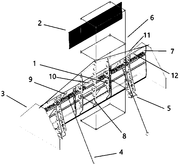
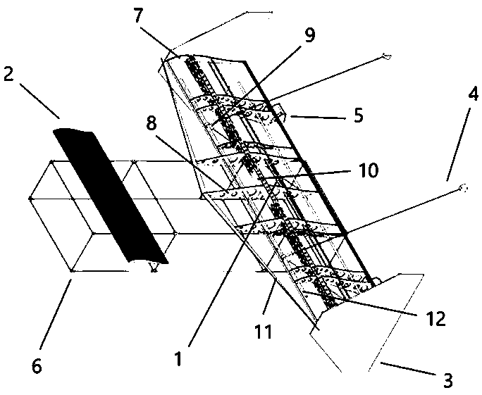
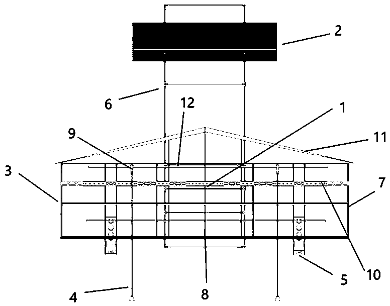
[0037] Such as Figure 1 to Figure 5 As shown, the numbers in the figure represent the main structural components of the aircraft. 1: Main wing; 2: Canard; 3: Stabilizer; 4: Foot support; 5: Vector motor seat; 6: Loading frame; 7: Outer s-shaped small rib; 8: Middle large rib (based on s modification of wing rib); 9: 3D printing; 10: main beam; 11: carbon leading edge; 12: front sub-beam.

[0038] The invention mainly includes a main wing 1, a vector motor base 5, a canard 2, a loading frame 6, a foot support 4 and an arduino-based mwc flight controller.

[0039] The main wing is a swept wing with an aspect ratio of 3.48 (sweep angle 79 degrees), providing the main lift. The canard is located at the front end of the main wing, which can increase the overall stall ang...


PUM


Abstract

The invention discloses a tailstock type vector differential biaxial aircraft. The tailstock type vector differential biaxial aircraft comprises a main wing, a vector motor base, a canard and an mwc flight controller. Sweepback wings are adopted as the main wing to provide main lift force. The canard is located at the front end of the main wing and used for increasing the overall stall angle of attack of the aircraft and providing lift force. The vector motor seat is arranged at the tail part of the main wing and is used for overcoming the flight resistance and self-gravity of the aircraft. The flight controller automatically detects the posture during hovering, and automatically changes the direction of the motor base and the rotating speed of the motor when the posture is abnormal, so that the motor base is stable. Characteristics of a rotor aircraft and a fixed-wing aircraft are combined, a vector technology is introduced, and a low-power engine is selected to be fixed to a vector motor base; double engines, a special airfoil profile, a moderate aspect ratio, canard wings and a wing end stabilizing surface are adopted, and the requirements for rapid small-attack-angle flight, hovering, low-speed large-attack-angle flight and rapid steering and attack angle change under a complex site can be met.

Description

technical field [0001] The invention relates to the field of vertical take-off and landing aircraft, in particular to a tailstock type vector differential two-axis aircraft. Background technique [0002] Most of the existing civil small aircraft are rotor-type and fixed-wing aircraft. Rotor-type aircraft can meet the low-speed flight work in various environments. This type of aircraft changes the flight attitude by changing the pitch of the propeller, which has low aerodynamic efficiency. , Low power load, difficult maneuvering, unstable flight, and the flight speed cannot be increased. However, fixed-wing aircraft need to reach a certain speed to take off, which cannot meet the requirements of low-speed flight missions, and have requirements for take-off and landing sites. Vector aircraft are mostly used in the military field, with the characteristics of high efficiency, good flexibility, and high adaptability to flight attitude, but they are rarely involved in civilian in...

Claims


Application Information

Patent Timeline
IPC IPC(8): B64C29/00B64C39/12B64D27/24B64C3/18
CPCB64C3/187B64C29/00B64C39/12B64D27/24
Inventor 翁煜侃孙在姚一飞沈思明
Owner CHINA JILIANG UNIV
Learn More