Bench work clamp device with automatic correction function for mold part machining

An automatic calibration and fixture device technology, applied in the field of fitters, can solve the problems of no automatic calibration of the position of the clamped object, inability to control the rotation speed well, and inconvenient operation for changing clamping molds, so as to improve convenience and application. Scope, time saving effect

Inactive Publication Date: 2020-04-03
广州利佳科技有限公司
View PDF8 Cites 4 Cited by
  • Summary
  • Abstract
  • Description
  • Claims
  • Application Information

AI Technical Summary

Problems solved by technology

[0003] The fitter clamp is a device for clamping molds and other items in the fitter operation. Most of the current fitter clamps can only be simple clamps to clamp the mold, and cannot adjust the clamping position according to the external structure of the object. Therefore, it can adapt to molds with different shapes. The current clamping device often does not have the function of automatically calibrating the position of the clamped object, which makes it quite inconvenient to adjust the position during the processing process. At the same time, most of the fitter clamps are often manually adjusted. It is very inconvenient to change the clamping mold, and the simple driving by the motor cannot control the rotation speed well, which will easily cause damage to the clamped mold when the motor rotates at a high speed.

Method used


Image

  • Bench work clamp device with automatic correction function for mold part machining
  • Bench work clamp device with automatic correction function for mold part machining
  • Bench work clamp device with automatic correction function for mold part machining

Examples


Embodiment 1

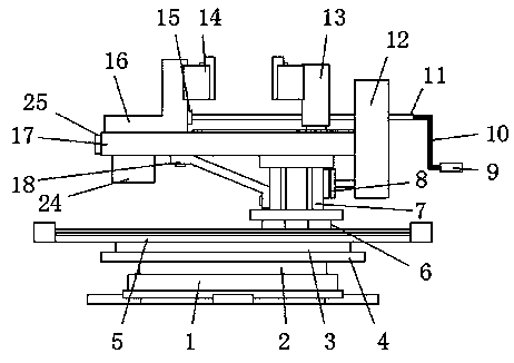
[0034] Example 1, such as Figure 5 , 6 : the motor 8 is controlled by the control panel 25, the output end of the motor 8 drives the first rotating rod 1206 to rotate, thereby driving the first gear 1201 to rotate, yes the first gear 1201 drives the second gear 1203 to rotate, and the second gear 1203 can rotate the The rotating speed is reduced by ten times, and the second gear 1203 drives the second rotating rod 1202 to rotate, thereby driving the third gear 1204 to rotate, and the third gear 1204 drives the fourth gear 1205 to rotate, and simultaneously the fourth gear 1205 reduces the rotating speed by ten times again. The four gears 1205 drive the screw rod 11 to rotate, through the screw thread between the screw rod 11 and the mobile table 13, the rotational torque is converted into the force that drives the mobile table 13 to move horizontally, so that the mobile table 13 moves, and the clamping structure 14 will be positioned at the mobile The mold between the table ...

Embodiment 2

[0035] Example 2, such as Figure 7 , 8 : The clamping structure 14 can be adjusted according to the shape of the mould. When the shape is a regular shape, it can be clamped directly through the splint 1404. When some arc-shaped molds need to be clamped, the splicing block 1403 and the splicing groove 1402 can be clamped. Separate, so that the splint 1404 is removed, and the arc-shaped mold is clamped through the arc-shaped groove 1405. When clamping some square molds, the clamping block 1406 can be pulled out from the inside of the square groove 23, and then the square mold is clamped. Set inside the square groove 23.

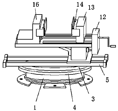
[0036] Working principle: Charge the battery before use, and the battery supplies power to the device during use. First, fix the base 1 at the designated position through the ear socket, and then fix the fitter fixture at the designated position. When the mold needs to be clamped, the mold can be placed Between the fixed platform 16 and the mobile platform 1...


PUM


Abstract

The invention discloses a bench work clamp device with an automatic correction function for mold part machining. The bench work clamp device comprises a base, a circular groove is formed in the top ofthe base, a rotating plate is arranged at the bottom end inside the circular groove, a circular friction plate is arranged above the rotating plate, a rubber ring is arranged at the top of the innerside of the circular groove, a circular mounting plate is mounted at the top of the circular friction plate, a scale needle is arranged at the edge position of the top of the circular mounting plate,two electromagnetic sliding rails are arranged at the top of the circular mounting plate, two electromagnetic sliding blocks are arranged at the top of each electromagnetic sliding rail, a mounting seat is arranged at the tops of the electromagnetic sliding blocks, a motor is arranged at one end of the mounting seat, and a rack is arranged at the top of the mounting seat. According to the bench work clamp device, the electromagnetic sliding rails and the electromagnetic sliding blocks are adopted for mounting, then the position of a clamping structure can be automatically adjusted after a moldis fixed, the clamping structure can be conveniently moved to a more convenient position, and better operation of a machining machine is facilitated.

Description

technical field [0001] The invention relates to the technical field of fitters, in particular to an automatic correcting fitter clamp device for mold parts processing. Background technique [0002] Fitter work mainly includes chiseling, filing, sawing, scribing, drilling, reaming, tapping and threading (see thread processing), scraping, grinding, straightening, bending and riveting, etc. The ancient metal processing technology, with the advancement of modern technology, more and more modern tools have been applied to various industrial technology fields, and the fitter field is no exception. [0003] The fitter clamp is a device for clamping molds and other items in the fitter operation. Most of the current fitter clamps can only be simple clamps to clamp the mold, and cannot adjust the clamping position according to the external structure of the object. Therefore, it can adapt to molds with different shapes. The current clamping device often does not have the function of a...

Claims


Application Information

Patent Timeline
IPC IPC(8): B25B1/10B25B1/18B25B1/22B25B1/24
CPCB25B1/10B25B1/18B25B1/22B25B1/24
Inventor 吴昌导
Owner 广州利佳科技有限公司
Why Eureka
Try Eureka