


Quick Research
Generate reliable direction feasibility study reports for your R&D in just a few steps.

Technical Q&A
Discover and master advanced knowledge NOW. Basics, ideas, possibilities, all at once.

Find Solutions
As an expert in R&D theories, this can generate solutions to your technical problems instantly.

Evaluate Feasibility
Analyze your overall solution with one click, know your potential R&D risks in advance.

Monitor Landscape
Get weekly tech updates, stay abreast of the latest tech innovations and key insights.
Cable working well
A technology for cable wells and cable pipes, which is applied in cable installation, cable installation in cable rooms, and cable installation in underground pipelines. It can solve problems such as uneven settlement and low investment, and achieve convenient construction and low investment. Less, solve the effect of uneven settlement
- Summary
- Abstract
- Description
- Claims
- Application Information
AI Technical Summary
Problems solved by technology
Method used
Image

Examples
Embodiment 1
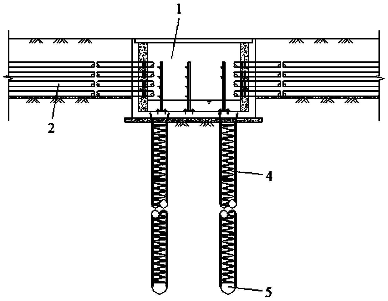
[0030] Embodiment one: as attached Figure 5 to attach Figure 7 As shown, a cable well includes a bottom plate 6 , a side wall 7 and a cover plate 8 enclosing the space in the well, and also includes a cushion 9 and a cable support 10 . The cable well includes four side walls 7, which are respectively a pair of opposite connecting side walls 7 and a pair of opposite supporting side walls 7, and the connecting side walls 7 are used for connecting cable pipes. The cushion layer 9 is disposed under the bottom plate 6 .
[0031] The bottom plate 6 has an overhanging portion 11 protruding from the outer edge of the side wall 7 along the extending direction of the cable duct, so that the bottom plate 6 constitutes an extended bottom plate 6 . The cable conduit also includes a balance portion 12 arranged on the outstretched portion 11 of the bottom plate 6 and used for balancing stress and supporting the cable conduit. The balance part 12 is formed by flakes or plain concrete, an...
PUM
 Abstract
Description
Claims
Application Information
 - R&D Engineer
- R&D Manager
- IP Professional
- Industry Leading Data Capabilities
- Powerful AI technology
- Patent DNA Extraction
Browse by: Latest US Patents, China's latest patents, Technical Efficacy Thesaurus, Application Domain, Technology Topic, Popular Technical Reports.
© 2024 PatSnap. All rights reserved.Legal|Privacy policy|Modern Slavery Act Transparency Statement|Sitemap|About US| Contact US: help@patsnap.com