Oil immersion device for manufacturing auto parts

A technology for spare parts and oil immersion, which is applied to the device and coating of the surface coating liquid, which can solve the problem of inability to immerse auto parts in oil, reduce the efficiency of auto parts immersion in oil, and the oil immersion device cannot meet actual needs, etc. problem, to achieve the effect of improving sufficiency, fast and fully immersing oil

Inactive Publication Date: 2021-06-18
东营瑞尔泰机电科技有限公司
View PDF0 Cites 0 Cited by
  • Summary
  • Abstract
  • Description
  • Claims
  • Application Information

AI Technical Summary

Problems solved by technology

[0003] At present, most of the existing oil immersion devices for the manufacture of auto parts on the market have the following deficiencies in the process of use: the oil immersion of auto parts only by simple immersion cannot fully and fully clean the auto parts. Rapid oil immersion reduces the oil immersion efficiency of auto parts. In summary, most of the existing oil immersion devices for auto parts manufacturing cannot meet actual needs well

Method used


Image

  • Oil immersion device for manufacturing auto parts
  • Oil immersion device for manufacturing auto parts
  • Oil immersion device for manufacturing auto parts

Examples


Embodiment 1

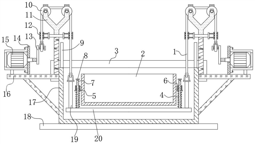
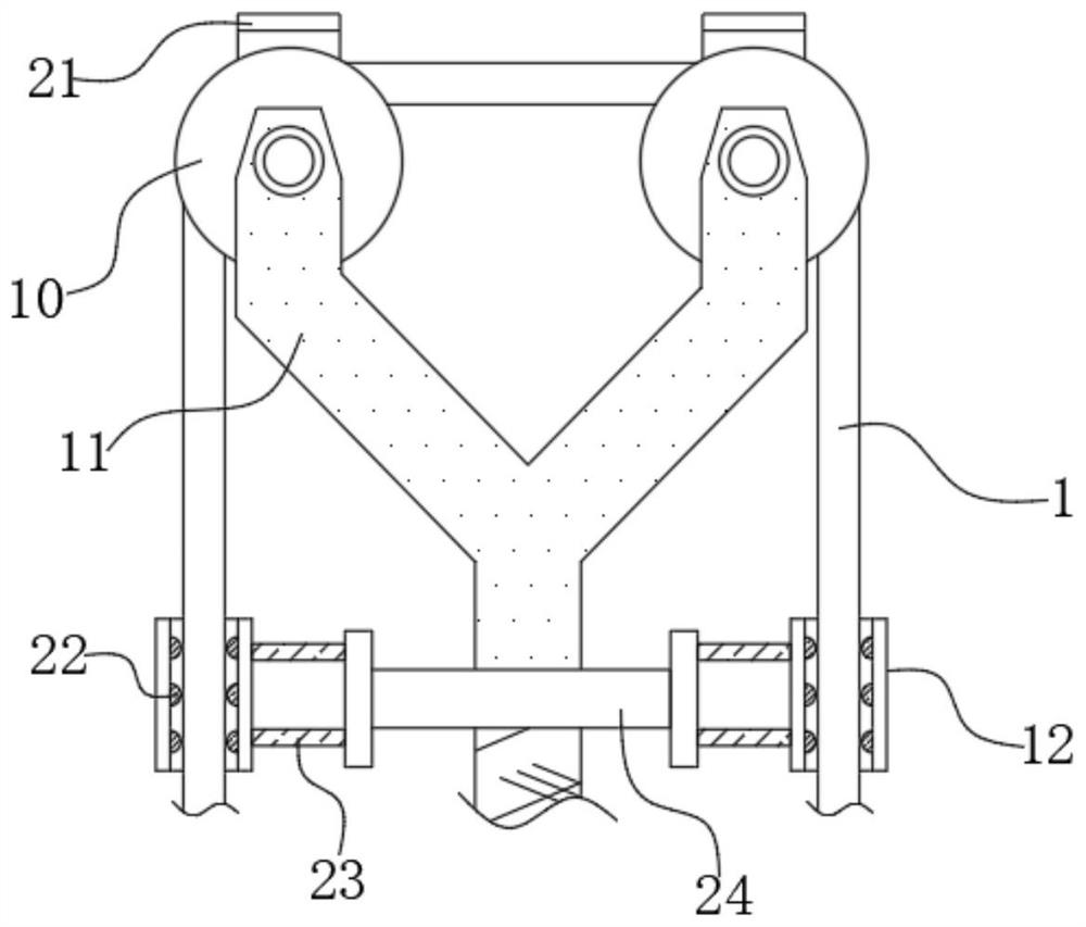
[0026] refer to Figure 1-3 , an oil immersion device for the manufacture of auto parts, comprising an oil immersion tank 17, lifting mechanisms are provided on both sides of the oil immersion tank 17, and a holding mechanism is arranged between the two lifting mechanisms. When immersing in oil, the lifting mechanism drives the holding mechanism The mechanism moves up and down so that the auto parts can be better immersed in oil. The holding mechanism includes a support plate 20. The top outer wall of the support plate 20 has multiple rows of through holes. The top outer wall of the support plate 20 is close to the four corners. Both are welded with a vertical rod 19, and the top of the vertical rod 19 is welded with a hanging ring. The side view structure of the hanging ring is an isosceles trapezoid, and the top outer wall of the supporting plate 20 is welded with two round rods 7 near the edges of both sides. The outer wall of the round rod 7 is sleeved with a spring 4, an ...

Embodiment 2

[0036] refer to Figure 4 , a kind of oil immersion device for the manufacture of auto parts. Compared with Embodiment 1, the main difference of this embodiment is that in this embodiment, the bottom inner wall of the cage 2 is welded with multiple rows of standpipes 26, and the top of the standpipe 26 is welded with The tapered plug 25 and the arc-shaped outer wall of the standpipe 26 are welded with multiple groups of annularly distributed leakage holes 27 .

[0037] During use, multi-row standpipe 26 makes auto parts be separated, avoids auto parts clumping, and the tapered plug 25 at the top of stand pipe 26 can prevent auto parts from accumulating on its top, and the outer wall of stand pipe 26 has leakage Hole 27, so it does not affect the flow of oil.


PUM


Abstract

The invention discloses an oil immersion device for manufacturing auto parts, which comprises an oil immersion tank, lifting mechanisms are arranged on both sides of the oil immersion tank, and a holding mechanism is arranged between the two lifting mechanisms, and the holding mechanism includes Supporting plate, the top outer wall of the supporting plate has multiple rows of through holes, the top outer wall of the supporting plate near the four corners is fixedly connected with vertical rods, the top of the vertical rods are fixedly connected with hanging rings, and the sides of the hanging rings As the structure is isosceles trapezoidal, two round rods are fixedly connected to the outer wall of the top of the supporting plate near the edges on both sides. The outer walls of the round rods are fitted with springs, annular plates and sliding sleeves. Between, the bottom of the annular plate is fixedly connected with the top of the spring. The invention relates to an oil immersion device for the manufacture of auto parts, which is convenient for workers to place auto parts, and can carry out reciprocating oil immersion up and down, and the oil immersion is sufficient.

Description

technical field [0001] The invention relates to the technical field of oil immersion devices, in particular to an oil immersion device for manufacturing auto parts. Background technique [0002] Auto parts are the various units that make up the whole car and a product that serves the car. It is one of the indispensable parts for assembling the car. During the production process of auto parts, some auto parts need to be soaked Oil, the oil immersion device needs to be used when immersing in oil. [0003] At present, most of the existing oil immersion devices for the manufacture of auto parts on the market have the following deficiencies in the process of use: the oil immersion of auto parts only by simple immersion cannot fully and fully clean the auto parts. Rapid oil immersion reduces the oil immersion efficiency of auto parts. In summary, most of the existing oil immersion devices for manufacturing auto parts cannot meet actual needs well. Contents of the invention [...

Claims


Application Information

Patent Timeline
Patent Type & Authority Patents(China)
IPC IPC(8): B05C3/10B05C11/10B05C13/02
CPCB05C3/10B05C11/1039B05C13/02
Inventor 杨又伦曹剑覃远福刘建华
Owner 东营瑞尔泰机电科技有限公司
Why Eureka
Try Eureka