Collecting device for geotechnical engineering exploration
A collection device and geotechnical engineering technology, applied in the direction of sampling devices, etc., can solve the problems of complex structure, inconvenient use, laborious operation, etc., and achieve the effect of simple operation, improved sampling efficiency, and rapid sampling
- Summary
- Abstract
- Description
- Claims
- Application Information
AI Technical Summary
Problems solved by technology
Method used
Image
Examples
Embodiment 1
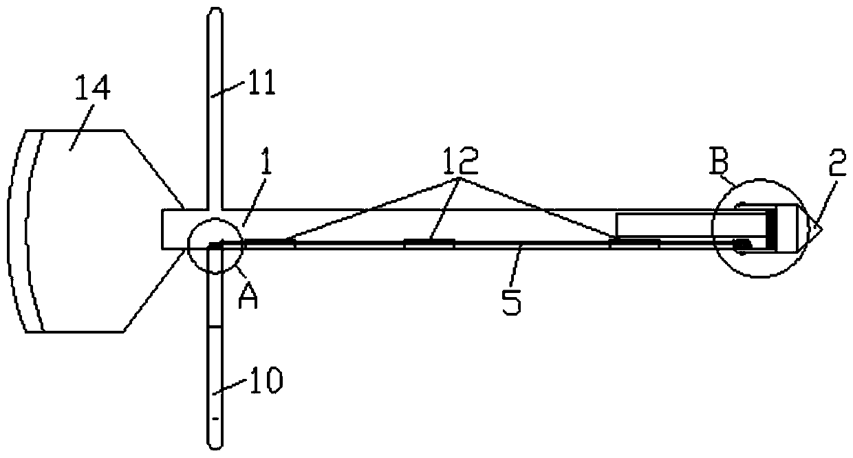
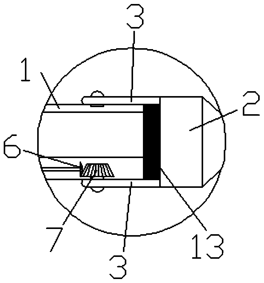
[0037] On the basis of the above structure, in this embodiment, the drill bit 2 is fixedly installed with a gasket 13 in a manner conceivable by those skilled in the art, such as strong glue, which is easy to replace; the gasket 13 is located between the drill bit 2 and the sampling tube 1 When the drill bit 2 is coaxial with the sampling tube 1, the sealing gasket 13 seals the open end of the sampling tube 1. After the sampling is completed, the open end of the sampling tube 1 is sealed by the gasket 13 to prevent the sample in the sampling tube 1 from leaking out.
[0038] Preferably, in this embodiment, the sealing gasket 13 is made of rubber material and has elasticity, so as to seal the open end of the sampling tube 1 and prevent the sample in the sampling tube 1 from leaking out.
Embodiment 2
[0040] On the basis of Embodiment 1, in this embodiment, the drill bit 2 is rotationally connected with the open end of the sampling pipe 1 through two oppositely arranged connecting plates 3, and one end of each connecting plate 3 is welded together with the drill bit 2, The other ends are rotatably connected with the open end of the sampling tube 1 through a rotating shaft. One side of the sampling tube 1 is fixedly connected with the limiting baffle 4, and when the drill bit 2 is coaxial with the sampling tube 1, one end of the limiting baffle 4 extends along the axial direction of the sampling tube 1 and extends to the side wall of the open end of the sampling tube 1 fit, one end of the limit baffle 4 is welded together with the drill bit 2. During the rotation of the drill bit 2, the drill bit 2 is limited by the limit baffle 4, so as to prevent the drill bit 2 from rotating arbitrarily and affecting the sampling.
Embodiment 3
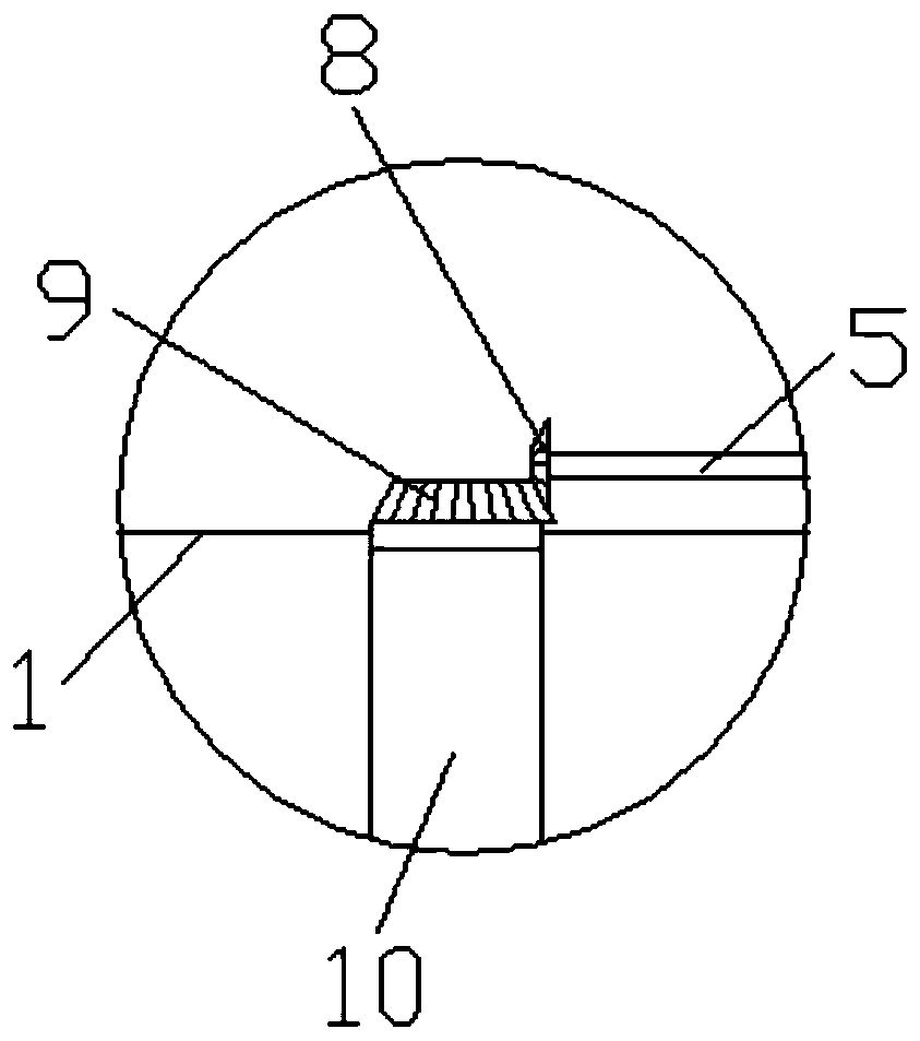
[0042] On the basis of Embodiment 1, in this embodiment, a transmission shaft 5 is installed rotatably in the sampling tube 1 along its axial direction, and a bevel gear 6 is coaxially fixed on one end of the transmission shaft 5. The way of connection; the open end of the sampling tube 1 is rotatably installed with a bevel gear 2 7, and the bevel gear 2 7 is connected to the drill bit 2 in transmission, specifically: one end of the rotating shaft connected to the connecting plate 3 extends to the sampling In the pipe 1, the bevel gear 2 7 is fixedly sleeved on one end of the rotating shaft through an interference connection, and the bevel gear 2 7 meshes with the bevel gear 1 6 . During sampling, turn transmission shaft 5 and drive bevel gear one 6 to rotate, and bevel gear one 6 drives bevel gear two 7 to rotate, to drive drill bit 2 to rotate, thereby change the relative position of drill bit 2 and sampling pipe 1, so that sample fast.
[0043]In addition, the inner wall of...
PUM
 Abstract
Description
Claims
Application Information
 - R&D
- Intellectual Property
- Life Sciences
- Materials
- Tech Scout
- Unparalleled Data Quality
- Higher Quality Content
- 60% Fewer Hallucinations
Browse by: Latest US Patents, China's latest patents, Technical Efficacy Thesaurus, Application Domain, Technology Topic, Popular Technical Reports.
© 2025 PatSnap. All rights reserved.Legal|Privacy policy|Modern Slavery Act Transparency Statement|Sitemap|About US| Contact US: help@patsnap.com


