
Quick connector for lamp

A technology for quick connection and lighting, which can be applied to lighting devices, fixed lighting devices, electric light sources, etc., and can solve the problems of lighting disassembly and maintenance, inconvenience

Inactive Publication Date: 2020-03-27
GUANGZHOU LEDIA LIGHTING CO LTD
View PDF6 Cites 0 Cited by
  • Summary
  • Abstract
  • Description
  • Claims
  • Application Information

AI Technical Summary

Problems solved by technology

The shell of this kind of line light is integrated with the light-emitting component. When the reflective light-emitting component fails, the entire lamp needs to be disassembled for maintenance, or when a different light-emitting component needs to be replaced, the entire lamp needs to be replaced, which is extremely inconvenient

Method used


Image

  • Quick connector for lamp
  • Quick connector for lamp
  • Quick connector for lamp

Examples


Embodiment Construction

[0027] The present invention will be further described below in conjunction with the accompanying drawings of the description.

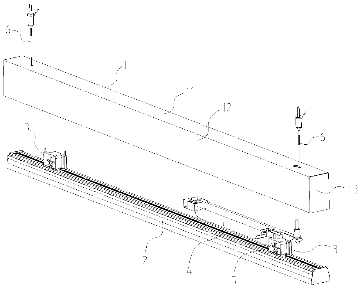
[0028] Such as figure 1 As shown, a line lamp includes a bracket 1, a power supply 4 fixed on the bracket 1, a lamp body 2 and a quick connector 3 fixed on the lamp body 2, and the lamp body 2 is fixed on the bracket through the quick connector 3 1 on.

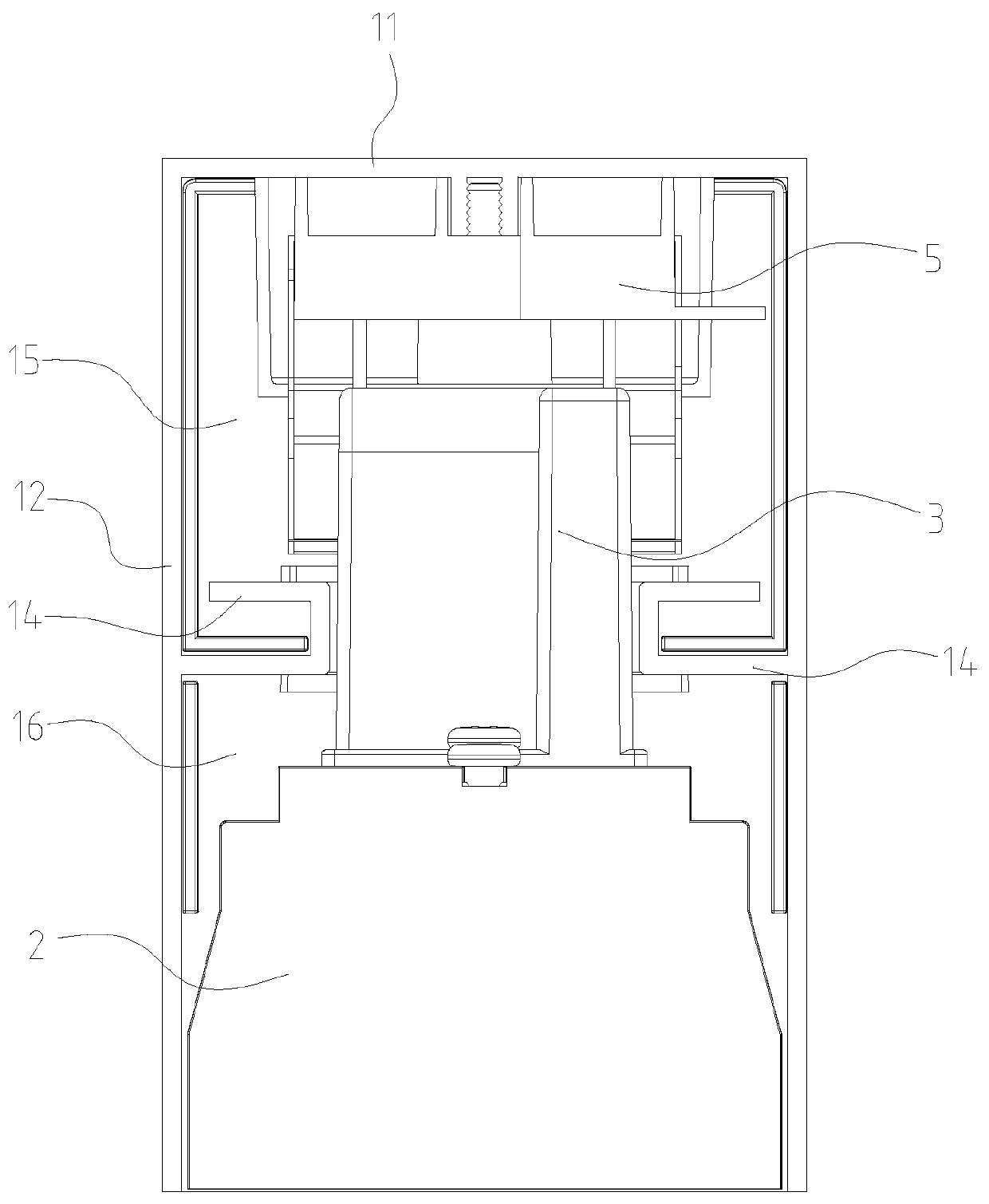
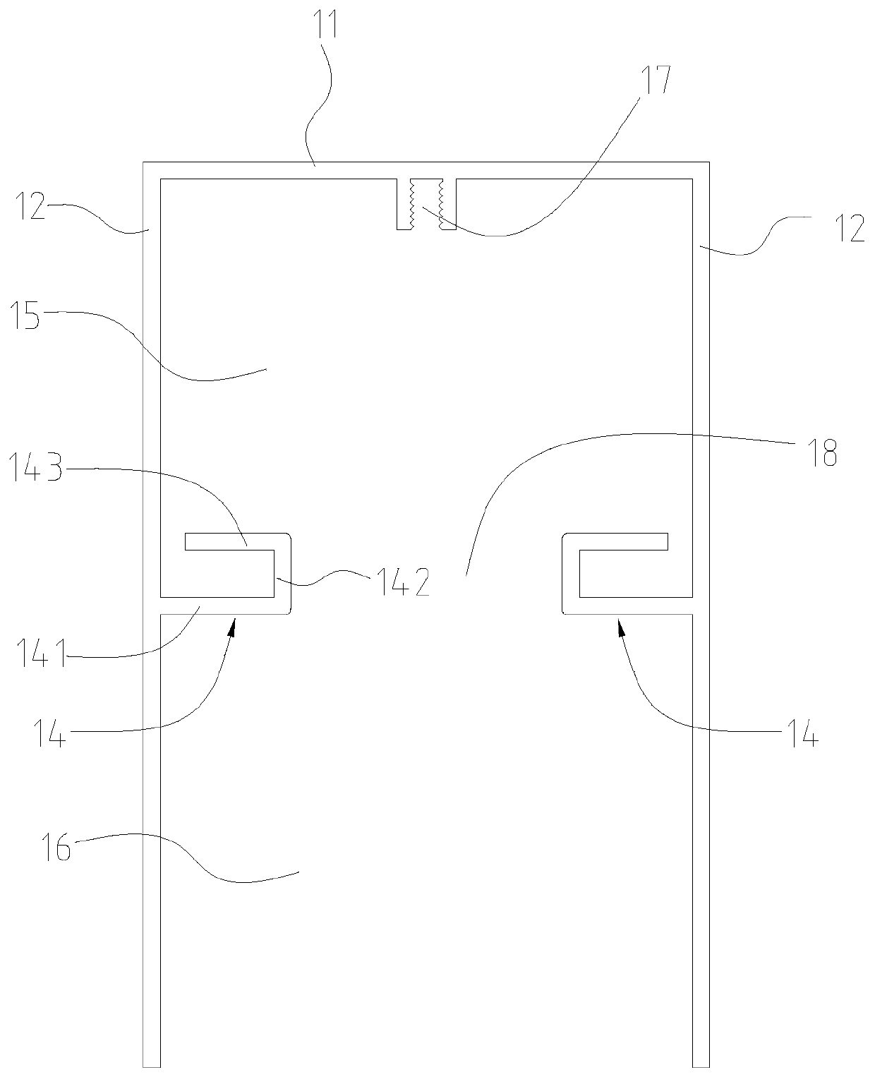
[0029] Such as figure 2 , 3 As shown, the support 1 is elongated, and it includes a top sealing plate 11, a side sealing plate 12 arranged on both sides of the width of the top sealing plate 11 and an end sealing plate 13 arranged at both ends of the length of the top sealing plate 11. The support 1 A long strip-shaped installation groove with a lower opening is formed inside. The inner wall of the side sealing plate 12 is provided with a positioning plate 14, and a channel 18 is formed between two opposite positioning plates 14; the positioning plate 14 and the bracket 1 are integrally stretche...


PUM


Abstract

A quick connector of a lamp comprises a cover body, a buckling piece, a gland, a base, a rotor and a rotating shaft; the installation action of the gland drives the rotor to rotate, the rotor drives the buckling piece to rotate through the rotating shaft, and therefore the opening and closing state of the buckling piece is achieved. Equal rotation of the rotor can be achieved by pressing the gland, the rotor drives the buckle piece to rotate by a quarter of a circle through the rotating shaft, and therefore the buckle locking state is achieved. The quick connector mounted on the lamp body canbe quickly disassembled from or assembled on the support, when the lamp body is maintained or replaced, the fixed support does not need to be disassembled, unlocking connection can be achieved only bypressing the quick connector, and convenience and quickness are achieved.

Description

technical field [0001] The invention relates to a lamp, in particular to a quick connector for a lamp. Background technique [0002] Line lights are generally suspended and installed on the ceiling by hanging wires or fixed on the wall by brackets; line lights generally include a shell and a light-emitting component located in the shell, such as the Chinese patent announcement number CN102762911B line light, which has a long bulb (2), wherein at least one lamp cap (6, 8) is provided for electrically contacting and holding the line lamp (1), and at least one light-emitting diode (16) is arranged in the bulb (2) as a light-emitting device and two heat sinks formed as plates (38, 40), wherein the at least one LED (16) is arranged on a circuit board (14) accommodated in the bulb (2), and the heat sink The device is configured to hold the circuit board (14), wherein two of the plates (38, 40) are respectively arranged at the end sections (18, 20) of the circuit board (14), where...

Claims


Application Information

Patent Timeline
IPC IPC(8): F21S8/06F21V19/04F21V23/06
CPCF21S8/061F21V19/04F21V23/06
Inventor 黄灿明吕鹤男杨艳春刘玉生
Owner GUANGZHOU LEDIA LIGHTING CO LTD
Learn More