
Intelligent lock unlocking and locking structure

A smart lock and lock structure technology, applied in the field of smart locks, can solve problems such as the door lock is difficult to open, affects the opening of the door lock, and cannot be easily opened again

Inactive Publication Date: 2021-08-10
易建华
View PDF10 Cites 0 Cited by
  • Summary
  • Abstract
  • Description
  • Claims
  • Application Information

AI Technical Summary

Problems solved by technology

[0003] At present, most of the common smart locks on the market use electronic lock cylinders or mechanical lock cylinders to lock the door. The advantages of electronic lock cylinders are that they are fast and convenient, and can be convenient for users to use. The problem is that the whole door lock will be difficult to open, and the advantage of the mechanical lock cylinder is that it is not easy to break down, but the mechanical lock cylinder is prone to rust due to the influence of the external environment and the passage of time, which will also affect the opening of the door lock. Most of the common door locks on the market use a single lock cylinder to lock the door. If a fault occurs, it cannot be easily opened again, which is inconvenient to use

Method used


Image

  • Intelligent lock unlocking and locking structure
  • Intelligent lock unlocking and locking structure
  • Intelligent lock unlocking and locking structure

Examples


Embodiment

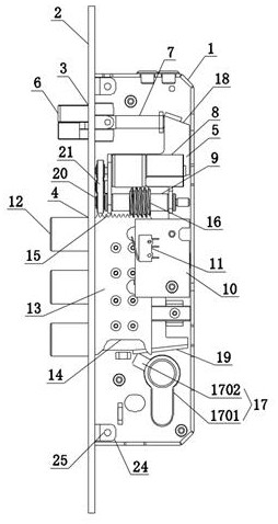
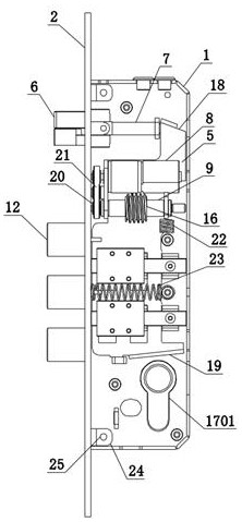
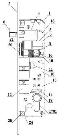
[0035] see Figure 1-6 , an intelligent lock unlocking and closing structure, including a lock body 1, the left side of the lock body 1 is fixedly connected with a connecting plate 2, and the left upper end of the connecting plate 2 is provided with a first lock hole 3, and the connecting plate 2 is provided with a first lock hole 3. The lower left end of the plate 2 is equidistantly opened with the second lock holes 4 of three sets of lock bolts. The inside of the lock body 1 is slidably connected with a slider 5 , and the inside of the first lock hole 3 is inserted with a triangular lock tongue 6. , the right side of the triangular deadbolt 6 is fixedly connected with a pull shaft 7, the other end of the pull shaft 7 is fixedly connected with the top of the slider 5, and the upper front end of the slider 5 is fixedly equipped with a motor 8, the The output end of the motor 8 is fixedly equipped with a worm rod 9, and the inner right side of the lock body 1 is fixedly connect...


PUM


Abstract

The invention discloses an intelligent lock unlocking and locking structure, and belongs to the field of intelligent locks. The intelligent lock unlocking and locking structure comprises a lock body, a connecting plate is fixedly connected to the left side of the lock body, a first lock hole is formed in the upper end of the left side of the connecting plate, second lock holes of three sets of plunger latches are formed in the lower end of the left side of the connecting plate at equal intervals, a sliding block is slidably connected to the interior of the lock body, a triangular spring bolt is inserted into the first lock hole, a pull shaft is fixedly connected to the right side of the triangular spring bolt, the other end of the pull shaft is slidably connected with the top of the sliding block, a motor is fixedly installed at the upper end of the front face of the sliding block, a worm is fixedly installed at the output end of the motor, a circuit board is fixedly connected to the right side of the interior of the lock body, a limiting stopper is fixedly installed on the left side of the front face of the circuit board, and fixed spring bolts are welded to the interiors of the second lock holes correspondingly. The first lock hole is used for installing the triangular spring bolt, the triangular spring bolt is connected with an inclined face through the pull shaft, and the sliding block is used for connecting operation of an internal mechanism of the lock body so as to complete unlocking and locking work.

Description

technical field [0001] The present invention relates to the field of intelligent locks, and more specifically relates to an intelligent lock unlocking and closing structure. Background technique [0002] Smart door lock refers to a lock that is improved on the basis of being different from traditional mechanical locks, and is more intelligent and simple in terms of user security, identification, and management. The smart door lock is the executive component for locking the door in the access control system. Different from traditional mechanical locks, smart door locks are composite locks with safety, convenience and advanced technology. [0003] At present, most of the common smart locks on the market use electronic lock cylinders or mechanical lock cylinders to lock the door. The advantages of electronic lock cylinders are that they are fast and convenient, and can be convenient for users to use. The problem is that the whole door lock will be difficult to open, and the a...

Claims


Application Information

Patent Timeline
Patent Type & Authority Applications(China)
IPC IPC(8): E05B15/00E05B15/10E05B47/00E05B63/14
CPCE05B15/00E05B15/10E05B15/108E05B47/0012E05B47/026E05B63/146
Inventor 易建华
Owner 易建华
Learn More