
Concentration device for solid-liquid separation dehydration

A solid-liquid separation and concentration device technology, which is applied in water/sewage multi-stage treatment, water/sludge/sewage treatment, flocculation/sedimentation water/sewage treatment, etc., can solve the problem of uncontrollable cost and low efficiency of solid-liquid separation , Stirring time is long and other problems, to achieve the effect of omitting energy consumption, improving efficiency and cost control

Pending Publication Date: 2020-03-27
象山德曼机械有限公司
View PDF0 Cites 2 Cited by
  • Summary
  • Abstract
  • Description
  • Claims
  • Application Information

AI Technical Summary

Problems solved by technology

[0003] The solid-liquid separation device used for sewage treatment is usually equipped with a concentrator, which is used to fuse the solid and liquid in the collected sewage, so as to improve the overall fluidity of the sewage. The traditional concentrator adopts a tank structure. The sewage is pumped into the concentration tank for stirring to achieve the purpose of fully merging the liquid and the solid. Although the concentration device of this structure realizes the full fusion of the liquid and the solid in the sewage, it has the following technical problems. Only a certain amount of sewage can be stored, and the concentration tank stirs the sewage for a long time, so the concentration tank can only intermittently provide sewage to the separation device, resulting in low solid-liquid separation efficiency, on the contrary, high energy consumption and cost also out of control

Method used


Image

  • Concentration device for solid-liquid separation dehydration
  • Concentration device for solid-liquid separation dehydration
  • Concentration device for solid-liquid separation dehydration

Examples


Embodiment Construction

[0029] The following are specific embodiments of the present invention and in conjunction with the accompanying drawings, the technical solutions of the present invention are further described, but the present invention is not limited to these embodiments.

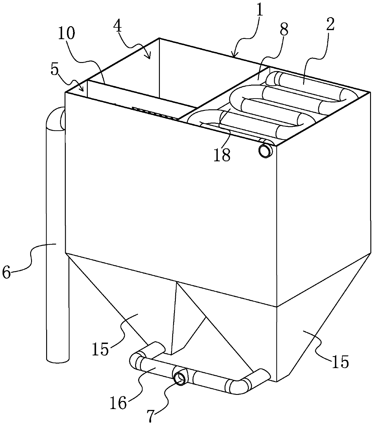
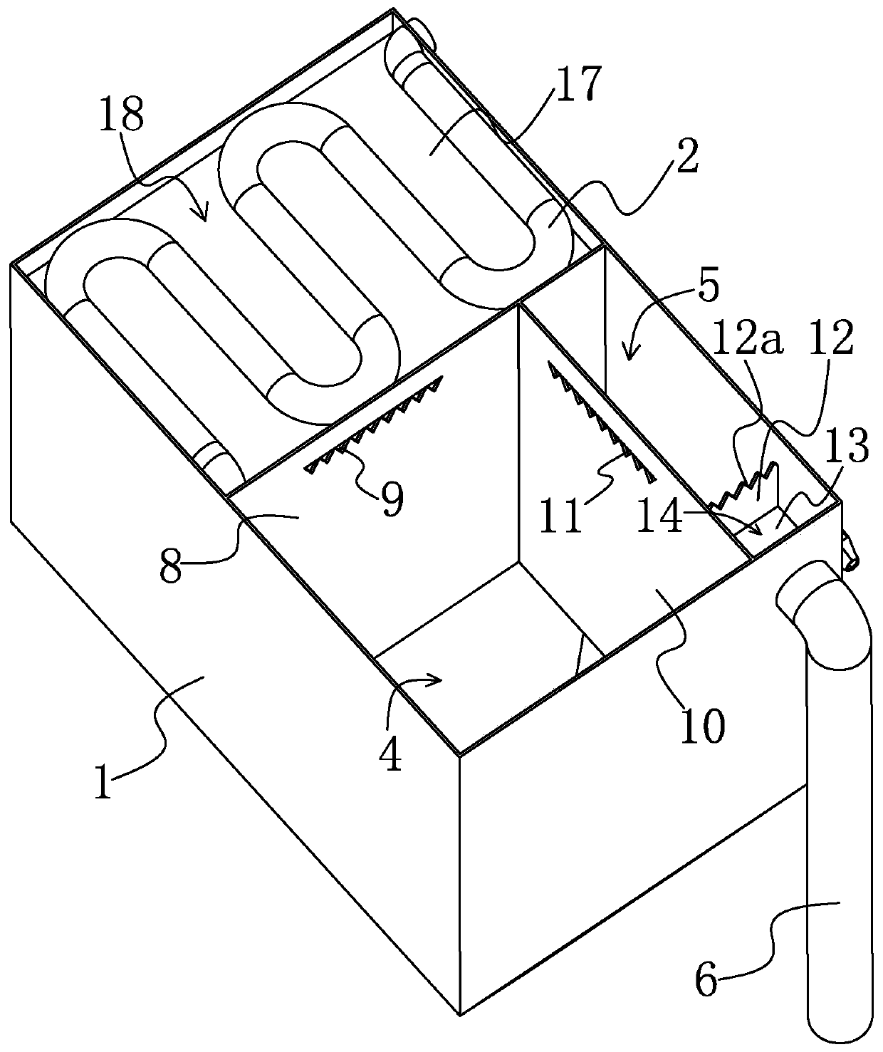
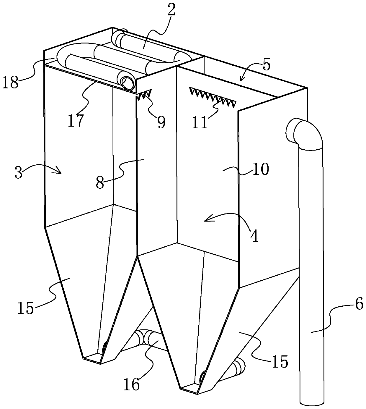
[0030] Such as Figure 1-Figure 3 As shown, the concentration device for solid-liquid separation and dehydration of the present invention includes a concentration tank 1 that is vertically arranged and is a square structure, and the top of the concentration tank 1 is provided with a flocculation pipe 2 communicated with a sewage delivery pipe (not shown in the figure), The concentration tank 1 is provided with a first concentration chamber 3, a second concentration chamber 4 and a third concentration chamber 5, the first concentration chamber 3 communicates with the flocculation pipe 2, the second concentration chamber 4 and the first concentration chamber 3 are separated and connected, The third concentrating chamber 5 is...


PUM


Abstract

The invention provides a concentration device for solid-liquid separation dehydration, and belongs to the technical field of sludge dehydration. The technical problem that an existing concentration device is low in solid-liquid separation efficiency and high in energy consumption is solved. The concentration device for solid-liquid separation dehydration comprises a concentration tank which is vertically arranged, a flocculation pipe which is arranged at the top of the concentration tank and is communicated with a sewage conveying pipe, a first concentration cavity which is positioned in the concentration tank and is communicated with the flocculation pipe, a second concentration cavity which is arranged in the concentration tank and is spaced apart from and communicated with the first concentration cavity, a third concentration cavity which is arranged in the concentration tank and is adjacent to and communicated with the second concentration cavity, a supernatant discharge pipe whichis fixedly arranged on the concentration tank and is communicated with the third concentration cavity, and a sludge outlet which is formed in the bottom of the concentration tank and is respectivelycommunicated with the first concentration cavity, the second concentration cavity and the third concentration cavity. The whole process can be realized through the flowing of sewage, the structure principle is simple, the energy consumption required by stirring is saved, the cost is controlled, and the efficiency is further improved.

Description

technical field [0001] The invention belongs to the technical field of sludge dewatering, and relates to a thickening device for solid-liquid separation and dehydration. Background technique [0002] The solid-liquid separation device is a compression filter device used to compress and dehydrate the raw materials or semi-processed products of processed food, or sludge and other hydrated substances. It is more commonly used for sewage treatment to achieve the purpose of environmental protection. [0003] The solid-liquid separation device used for sewage treatment is usually equipped with a concentrator, which is used to fuse the solid and liquid in the collected sewage, so as to improve the overall fluidity of the sewage. The traditional concentrator adopts a tank structure. The sewage is pumped into the concentration tank for stirring to achieve the purpose of fully merging the liquid and the solid. Although the concentration device of this structure realizes the full fusio...

Claims


Application Information

Patent Timeline
IPC IPC(8): C02F9/04
CPCC02F1/52C02F2001/007
Inventor 毛克峰
Owner 象山德曼机械有限公司
Learn More