Arrangement and method for interference correction of imaging flow measurements

A flow measurement and imaging technology, applied in measuring devices, liquid/fluid solid measurement, measuring flow/mass flow, etc., can solve problems such as multiple reflections, unable to form boundary surfaces, and impossible to correct the field of view instantaneously, and achieve a simple structure Effect

Active Publication Date: 2020-12-08
DRESDEN UNIVERSITY OF TECHNOLOGY
View PDF4 Cites 0 Cited by
  • Summary
  • Abstract
  • Description
  • Claims
  • Application Information

AI Technical Summary

Problems solved by technology

Scattering of light on tissue results in multiple reflections, which prevent any defined boundary surfaces from forming
Disadvantageously, the correction of optical distortions on the retina can thus only be performed in sections, ie line by line and thus on a small scale, since the first module has a line scanner for scanning the eye for this purpose
It is therefore impossible to correct the entire field of view instantaneously

Method used


Image

  • Arrangement and method for interference correction of imaging flow measurements
  • Arrangement and method for interference correction of imaging flow measurements
  • Arrangement and method for interference correction of imaging flow measurements

Examples


Embodiment Construction

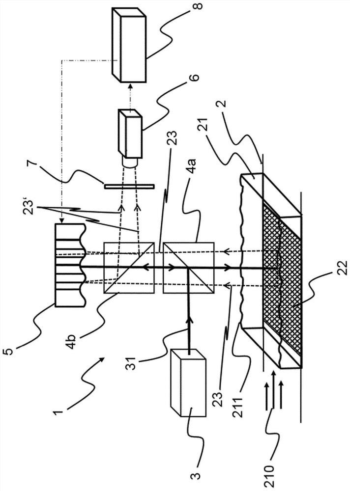
[0109] figure 1 An exemplary embodiment of a wavefront-free sensor arrangement 1 for correcting optical disturbances by undulating boundary surfaces 211 in imaging flow measurement methods is shown. A fluid 21 flows through the flow channel 2 in a flow direction 210 , wherein the fluid 21 has an open boundary surface 211 facing the environment. Scattering at the open boundary surface 211 thus causes fluctuating optical disturbances. For measurement by means of imaging flow measurement methods, the fluid 21 contains scattering particles (not shown). A static pattern 22 is provided at the bottom of the flow channel 2 .

[0110] The illumination source 3 emits illumination light 31 which is guided via the beam splitter 4a and the further beam splitter 4b to the surface light modulator 5 and thus reflected in the direction of the flow channel 2 in order to illuminate through the boundary surface 211 Flow fluid 21 and pattern 22 . In the exemplary embodiment, the measurement fi...


PUM

PropertyMeasurementUnit
diameteraaaaaaaaaa

Abstract

Optical interference is generated by often time-varying boundary surfaces between flowing fluids with different refractive indices, such as a boundary surface between water and air with an open water surface. Optical flow measurement processes through boundary surfaces are affected by such disturbances, which can lead to significant measurement deviations or may even completely prevent the performed measurements. The present invention helps to solve this metrology problem by proposing an arrangement (1, 1a, 1') and method for instantaneous and hardware-based correction of optical disturbances caused by undulating boundary surfaces (211). To this end, a wavefront modulator (5) is introduced into the beam path of the optical measuring method, which modulator actively compensates for optical disturbances by means of a control system. The invention enables light flow measurements through undulating boundary surfaces. It is not limited to a single flow measurement technique, but can be implemented in all known imaging methods. The invention can be used in a variety of technical applications. Some examples include: liquid-air boundary surfaces, such as in water channels with open surfaces; thin-film flow, such as in process technologies for cooling, purification, or distillation; fluid jets, whose surfaces undulate on all sides; Measurement of air bubbles present in suspended droplets or droplets or liquids adhered to opaque substrates. The invention is also suitable for correcting disturbances due to temperature gradients in combustion, pressure gradients such as in pressure fluctuations or concentration gradients such as in electrolytic processing.

Description

technical field [0001] The present invention relates to an arrangement and a method for interference correction of a flow measurement method, in particular an arrangement and a method for interference correction of an imaging flow measurement method. Background technique [0002] Many treatments in chemical engineering involve fluids with different refractive indices separated by boundary surfaces. This boundary surface typically changes with time. The resulting refractive index fluctuations represent time-varying fluctuating optical disturbances. This can greatly reduce the performance of the optical measurement method or make the measurement impossible at all. For example, in an open surface in a pool where waves may form, light rays are randomly refracted at the water-air boundary surface, and using this boundary surface to measure flow velocity in water is heavily affected by disturbances. Fluctuating boundary surfaces are therefore a major challenge for flow measurem...

Claims


Application Information

Patent Timeline
Patent Type & Authority Patents(China)
IPC IPC(8): G02B26/06G01N21/03G02B27/00
CPCG02B26/06G02B27/0068G01F1/661
Inventor 拉尔斯·比特纳于尔根·察尔斯克马丁·泰希内克塔里奥斯·库库拉基斯
Owner DRESDEN UNIVERSITY OF TECHNOLOGY
Why Eureka
Try Eureka