
Elevator door control device and elevator door drive system

A door control and door drive technology, which is applied in the field of elevator door control devices, can solve problems such as mechanism damage, inability to move accurately, and longer door moving time

Active Publication Date: 2020-03-24
HITACHI LTD
View PDF12 Cites 1 Cited by
  • Summary
  • Abstract
  • Description
  • Claims
  • Application Information

AI Technical Summary

Problems solved by technology

When the speed tracking performance is low, a position error occurs along with the speed error, so the door cannot move exactly the desired distance corresponding to the speed command
As a result, the deceleration start position of the door deviates from the predetermined position, so the door collides with the open end or the closed end, or the time it takes for the door to move to the open end or the closed end becomes longer.
In addition, when the vibration suppression performance is low, the door vibrates to generate noise, or resonance occurs at a low frequency to damage the mechanism

Method used


Image

  • Elevator door control device and elevator door drive system
  • Elevator door control device and elevator door drive system
  • Elevator door control device and elevator door drive system

Examples


Embodiment 1

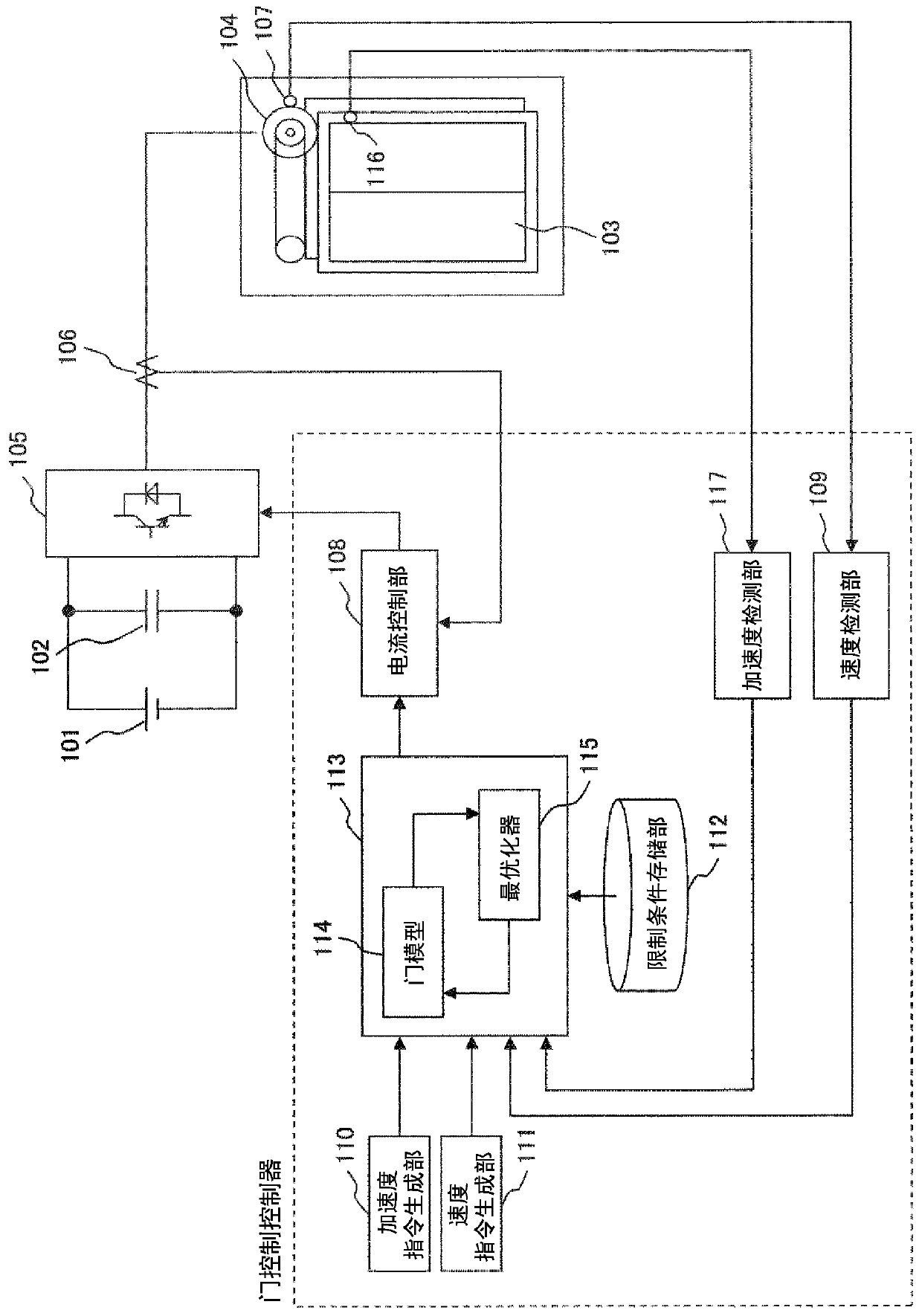
[0036] figure 1 It is a diagram showing the overall configuration of a door drive system of an elevator including a door control device (door control controller) as Embodiment 1 of the present invention.

[0037] figure 1 Among them, 103 is an elevator car that ascends and descends between floors, and the door mechanism of the car 103 is constituted by constituent elements 101 , 102 , 104 to 107 . 101 denotes a DC power supply, 102 denotes a DC capacitor charged by the DC power supply 101, 104 denotes a door motor that opens and closes the door of the car 103, 105 denotes an inverter device that drives the door motor 104, and 106 denotes the flow to the door motor 104. 107 represents a rotary encoder for detecting the rotational speed and rotor position of the door motor 104 . In the first embodiment, a permanent magnet synchronous motor is used as the door motor 104 .

[0038] It should be noted that, as a constituent element of the door mechanism, there is also an endless...

Embodiment 2

[0102] Image 6 It is a diagram showing the overall configuration of a door driving system of an elevator including a door control device (door control controller) as a second embodiment of the present invention. Hereinafter, points different from Embodiment 1 will be mainly described.

[0103] In the second embodiment, the position pattern (position command) generated by the position command generation unit 201 is input to the optimal control unit 113 . In addition, the position detection unit 203 integrates the speed information output from the speed detection unit 109 to calculate the position (movement distance) of the door (or motor). The calculated position information is input to the optimal control unit 113 as a position feedback value.

[0104] The optimal control unit 113 generates a speed command by solving the optimal control problem based on the position command and the acceleration command generated by the acceleration command generation unit 110, and outputs i...


PUM


Abstract

Provided are an elevator door control device that has the ability for both speed tracking and vibration suppression and that can ensure safety, and an elevator door drive system using same. An elevator door control device comprises: a control unit (108) that outputs, in accordance with a target command for a door operating state, a control command for driving a door mechanism provided on an elevator door (103) and that creates the control command in accordance with control input; and an optimization control unit (113) that has an evaluation index to evaluate the door operating state and the control input together, that calculates the control input to optimize the evaluation index, and that outputs the calculated control input to the control unit.

Description

technical field [0001] The present invention relates to an elevator door control device and an elevator door drive system using the elevator door control device. Background technique [0002] The door control device of the elevator is installed on the side of the car, and controls the opening and closing of the door by using the power of the motor to slide the door panel. [0003] The door panel is combined with an endless belt (V-belt, toothed belt, etc.) wound on pulleys or a steel wire sling. When the power of the motor is used to drive the belt or steel wire sling, the door panels will move together and slide left and right. [0004] The door panels are suspended from door guide rails provided above the car entrance. In addition, a door shoe provided at a lower portion of the door panel is slidably engaged with a groove of a sill of the car floor portion. The door panel is guided by the groove of the door rail and the sill, and slides in a certain direction without de...

Claims


Application Information

Patent Timeline
IPC IPC(8): B66B13/14
CPCB66B13/143
Inventor 井上真辅照沼智明大沼直人
Owner HITACHI LTD
Learn More