
Modeling method for NX Klingelnberg cycloid bevel gear

A modeling method and technology of bevel gears, applied in geometric CAD and other directions, can solve problems such as inconvenient processing of tooth end face rounding, model tooth shape distortion, and low modeling efficiency

Active Publication Date: 2020-03-24
NANJING HIGH SPEED & ACCURATE GEAR GRP
View PDF1 Cites 1 Cited by
  • Summary
  • Abstract
  • Description
  • Claims
  • Application Information

AI Technical Summary

Problems solved by technology

[0002] At present, the existing Klingenberg bevel gear modeling methods mostly simplify the process of additive modeling. It first replaces the actual cycloid on the conical surface with the projection of the oblique line on the conical surface, and then uses the additive method Modeling, that is, sweeping a tooth, and finally arraying this tooth, this type of modeling method has the following disadvantages: the first is that the actual gear is manufactured as a tooth cutting process, and the array teeth are seriously inconsistent with the actual; the second is Replacing the cycloid on the conical surface with oblique projections on the conical surface is also seriously inconsistent with the reality, and the generated model tooth shape is distorted, which is easy to misunderstand the tooth shape; the third is that the large end surface of the gear shaft cannot be processed It is also extremely inconvenient to deal with the rounding of the shaft segment and the rounding of the tooth end face; the fourth is that the gear shaft hob marks cannot be processed; the fifth is that the modeling efficiency is low, and the teeth that are generally swept in an array need It consumes more computer memory and time; the sixth is the existing modeling method, the generated Klingenberg cycloid bevel gear model is mostly one-time, or needs to regenerate other parameters Klingenberg cycloid For bevel gears, a large number of modifications are required and the ability to be compatible with other parameters is poor, that is, when changing its parameters with this model, the model often has errors

Method used


Image

  • Modeling method for NX Klingelnberg cycloid bevel gear
  • Modeling method for NX Klingelnberg cycloid bevel gear

Examples


Embodiment Construction

[0076] The following will clearly and completely describe the technical solutions in the embodiments of the present invention with reference to the accompanying drawings in the embodiments of the present invention. Obviously, the described embodiments are only some, not all, embodiments of the present invention. Based on the embodiments of the present invention, all other embodiments obtained by persons of ordinary skill in the art without making creative efforts belong to the protection scope of the present invention.

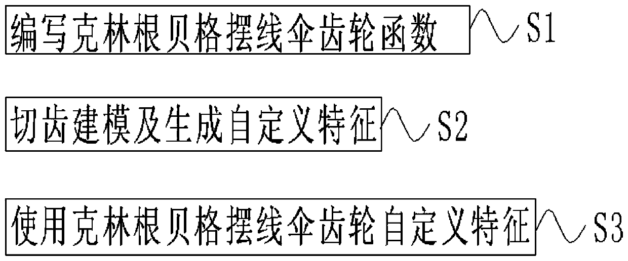
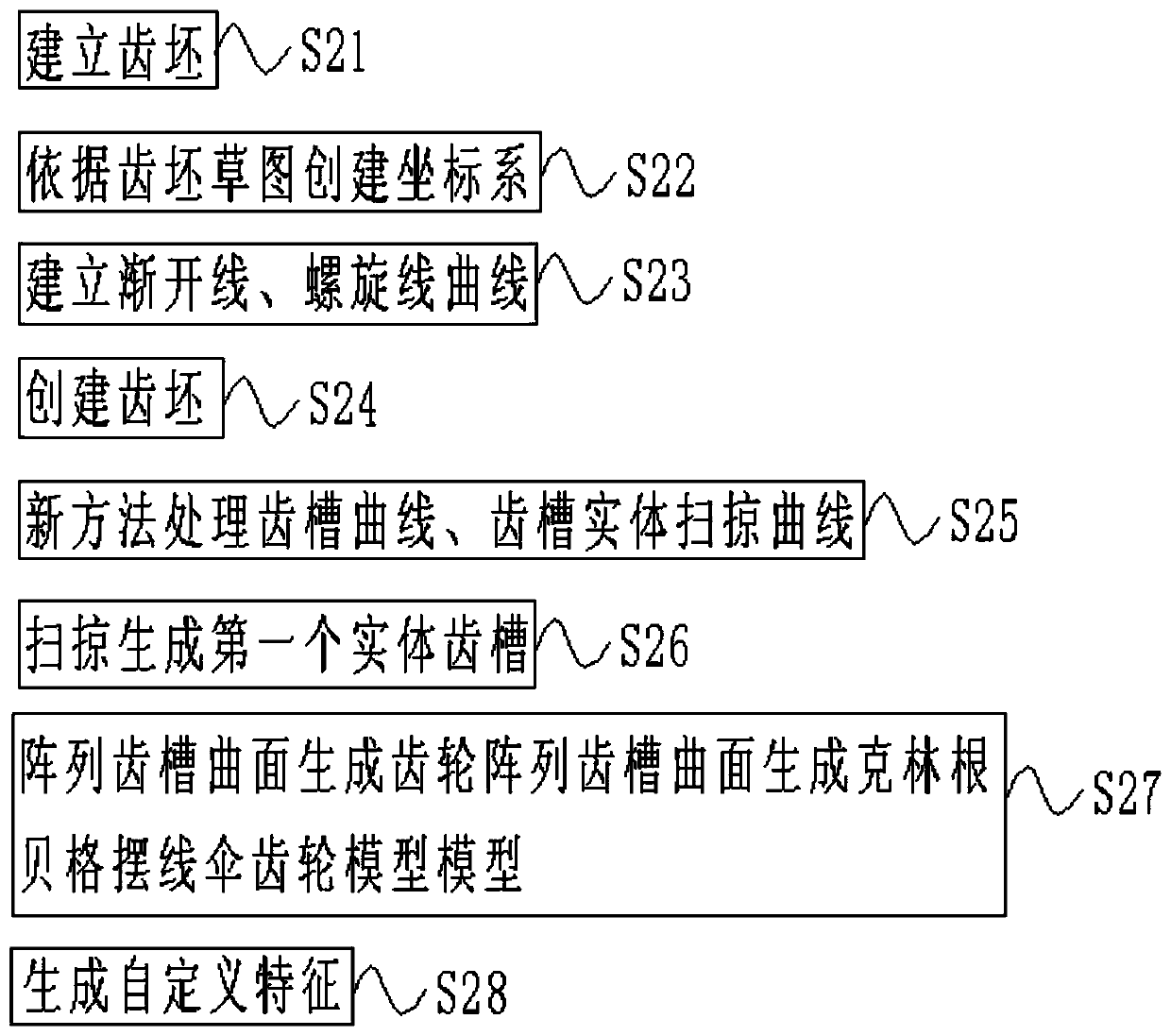
[0077] see Figure 1~2 , in an embodiment of the present invention, an NX Klingenberg cycloidal bevel gear modeling method,

[0078] Step S1: Write the Klingenberg cycloid bevel gear function:

[0079] Basic input parameters: large gear big end indexing circle diameter D02=580, driving gear teeth number z1=12, driven gear teeth number z2=41, helix angle βm=35, shaft intersection angle Σ=90, driving gear tooth height variation coefficient Xh =0.44, driving wh...


PUM


Abstract

The invention discloses a modeling method for an NX Klingelnberg cycloid bevel gear. The model generated by the modeling method can realize model generation of any gear pair parameters, support angular displacement and shear displacement gear models, and realize free switching between a driving gear and a driven gear of the same model. Free switching between the left rotation direction and the right rotation direction can be achieved, only basic parameters need to be changed when the gear model is generated each time, and only 3-4 seconds are needed for generating the model, the problems thatin three-dimensional design, the consumed time of modeling of the Klingelnberg bevel gear each time is long, and many repeated steps are needed are effectively solved, and the generated model is highin fault tolerance, generation success rate and parameter accuracy.

Description

technical field [0001] The invention relates to the field of gear modeling, in particular to an NX Klingenberg cycloid bevel gear modeling method. Background technique [0002] At present, the existing Klingenberg bevel gear modeling methods mostly simplify the process of additive modeling. It first replaces the actual cycloid on the conical surface with the projection of the oblique line on the conical surface, and then uses the additive method Modeling, that is, sweeping a tooth, and finally arraying this tooth, this type of modeling method has the following disadvantages: the first is that the actual gear is manufactured as a tooth cutting process, and the array teeth are seriously inconsistent with the actual; the second is Replacing the cycloid on the conical surface with oblique projections on the conical surface is also seriously inconsistent with the reality, and the generated model tooth shape is distorted, which is easy to misunderstand the tooth shape; the third i...

Claims


Application Information

Patent Timeline
Patent Type & Authority Applications(China)
IPC IPC(8): G06F30/17
CPCY02T90/00
Inventor 李宁波张海
Owner NANJING HIGH SPEED & ACCURATE GEAR GRP
Learn More