
Modular floor heater and air conditioner all-in-one machine

A modular, all-in-one technology, applied in air conditioning systems, heating methods, space heating and ventilation, etc., can solve problems affecting the heating effect of floor heating, and achieve the effect of keeping a clear mind

Active Publication Date: 2020-03-24
海普电器有限公司
View PDF7 Cites 4 Cited by
  • Summary
  • Abstract
  • Description
  • Claims
  • Application Information

AI Technical Summary

Problems solved by technology

[0002] The existing air energy heat pump triple supply unit, that is, the integrated unit of air conditioning, floor heating and hot water, can not only realize the independent use of air conditioning and floor heating, but also realize the simultaneous cooling or heating of air conditioning and floor heating. However, when the floor heating is turned on in winter, after Floor heating conducts heat to the ground for a long time, which will make users feel stuffy. If you open the window for ventilation, because the temperature is low in winter, the cold wind blowing in is too cold, which will make people feel uncomfortable and affect the heating effect of floor heating. Realize the cooling of the air conditioner and the heating of the floor heating, forming the effect of top cooling and bottom heating, so that the air conditioner blows out a more suitable low temperature combined with floor heating heating, which will make people feel comfortable, especially at work, which will keep users clear. Most air energy heat pump tri-generation units cannot realize the mode of air conditioning refrigeration and floor heating heating at the same time

Method used


Image

  • Modular floor heater and air conditioner all-in-one machine
  • Modular floor heater and air conditioner all-in-one machine
  • Modular floor heater and air conditioner all-in-one machine

Examples


no. 1 example

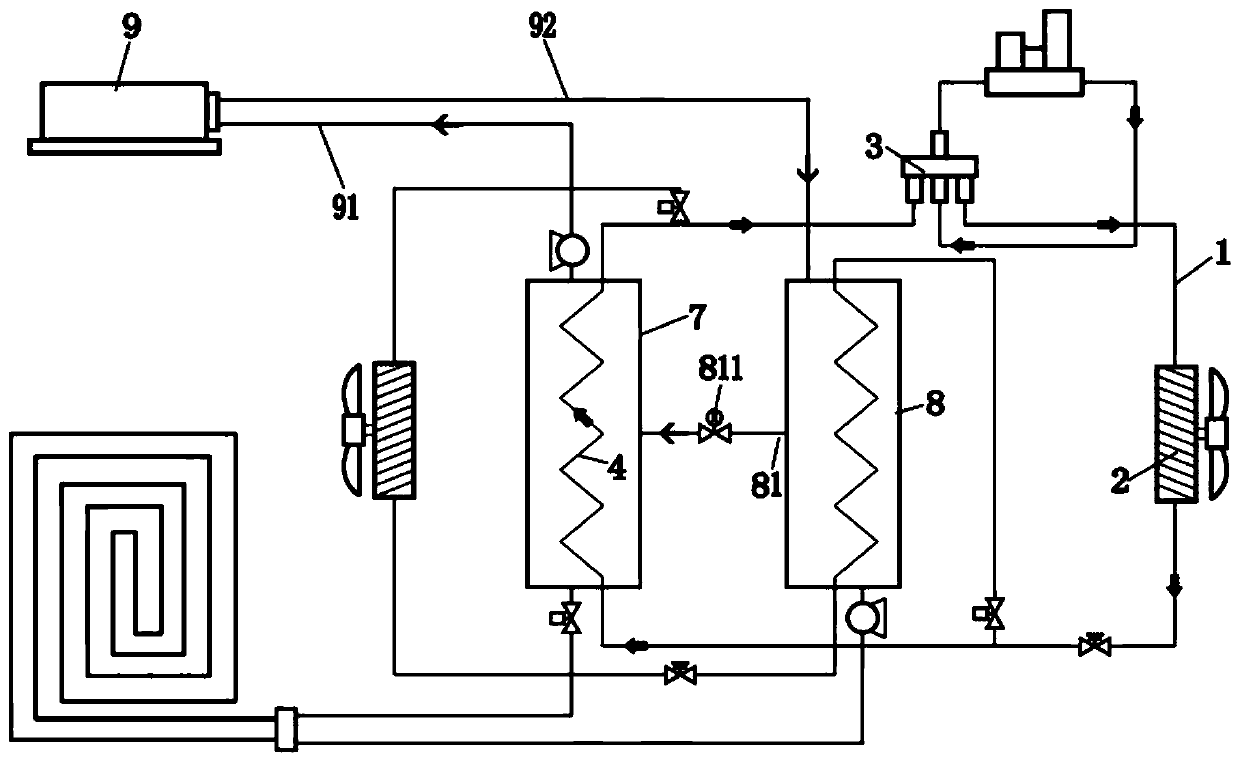
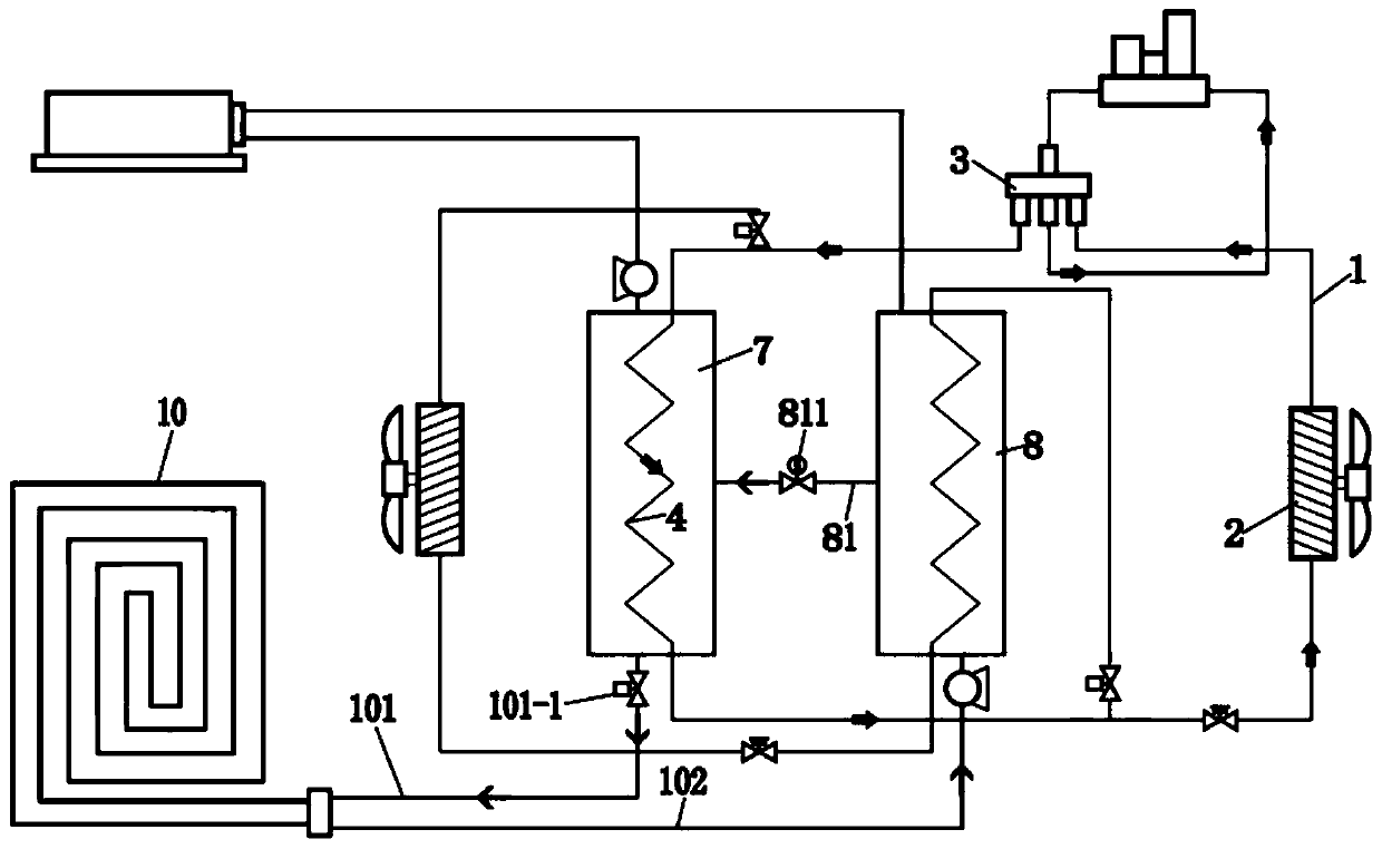
[0032] Such as figure 1 As shown, the modular floor heating and air conditioning integrated machine includes: refrigerant circulation pipeline 1, evaporator 1, 2, four-way valve 3, heat exchanger 1 4, evaporator 2 5, heat exchanger 2 6, water tank 1 7, water tank 28. Fan coil unit 9, floor heating circulation pipeline 10;

[0033] The refrigerant circulation pipeline 1 is connected with an evaporator-2, a four-way valve 3, a compressor, a heat exchanger-4, and a throttle valve, wherein the refrigerant circulation pipeline 1 is located between the four-way valve 3 and the heat exchanger-4. The part between is equipped with a refrigerant circulation pipeline;

[0034] The first branch of the refrigerant circulation pipeline is connected to the evaporator two 5, another throttle valve, and the heat exchanger two 6 in sequence, and the extended end of the first refrigerant circulation pipeline is connected to the heat exchanger one 4 and the throttle valve The refrigerant circul...

no. 2 example

[0047] Modular floor heating and air conditioning integrated machine, including: refrigerant circulation pipeline 1, evaporator 2-1, four-way valve 3, heat exchanger 4-1, water tank 1 5-1, water tank 2 6-1, water pipe 7-1 , circulation pipeline 8-1, fan coil unit 9, floor heating circulation pipeline 10;

[0048] The refrigerant circulation pipeline 1 is sequentially connected to the evaporator 2, the four-way valve 3, the compressor, the heat exchanger 4, and the throttle valve;

[0049] Change the flow direction of the refrigerant through the four-way valve 3, so that the heat exchanger 4 can absorb heat and release heat or absorb cold and release heat;

[0050] The water tank one 5-1 accommodates the heat exchanger 4;

[0051] The first water tank 5-1 communicates with the second water tank 6-1 through the flow pipeline 7-1, and the second water tank 6-1 communicates with the evaporator 2-1 through the circulation pipeline 8-1, wherein the circulation pipeline 8-1 communic...

Embodiment approach

[0058] Preferably, as an implementable manner, a water barrier 11-1 is provided in front of the evaporator 2-1 to prevent water from overflowing when flowing along the evaporator 2-1.

[0059] The working principle of this embodiment:

[0060] The flow direction of the refrigerant is changed through the four-way valve 3 to realize separate cooling and heating of the fan coil unit 9 and the floor heating circulation pipeline 10 or joint cooling and heating. When the fan coil unit 9 needs to be turned on for cooling, the floor heating circulation pipeline 10 is used for heating mode, such as Figure 10 As shown, the circulating water pump 1 8-11 is turned on, the water in the water tank 2 6-1 flows into the evaporator 2-1 along the circulating pipeline 8-1, exchanges heat with the evaporator 2-1, cools down, and flows into the water tank again In the second 6-1, the heat exchanger 4-1 heats the water in the water tank one 5-1 at the same time, the three-way valve 91-11 closes t...


PUM


Abstract

The invention relates to the field of central air conditioning systems, in particular to a modular floor heater and air conditioner all-in-one machine. The machine comprises a refrigerant circulatingpipeline, a first evaporator, a four-way valve, a first heat exchanger, a second evaporator, a second heat exchanger, a first water tank, a second water tank, a fan coiler and a floor heater circulating pipeline; the refrigerant circulating pipeline is provided with the first evaporator, the four-way valve, the first heat exchanger, the second evaporator and the second heat exchanger; the first heat exchanger and the second heat exchanger are wrapped by the first water tank and the second water tank; and the first water tank and the second water tank communicate with the fan coiler and the floor heater circulating pipeline. The machine sets cold water or hot water flowing directions according to different molds to realize common or single heating and refrigeration, cannot make people feelstuffy through refrigeration by the fan coiler and heating by the floor heater circulating pipeline, and adjusts the temperature of water in the second water tank through mutual flowing of the water in the first water tank and the second water tank to enable the fan coiler to refrigerate indoors at a proper temperature.

Description

technical field [0001] The invention relates to the field of central air-conditioning systems, in particular to a modular floor heating and air-conditioning integrated machine. Background technique [0002] The existing air energy heat pump triple supply unit, that is, the integrated unit of air conditioning, floor heating and hot water, can not only realize the separate use of air conditioning and floor heating, but also realize the simultaneous cooling or heating of air conditioning and floor heating. However, when the floor heating is turned on in winter, after Floor heating conducts heat to the ground for a long time, which will make users feel stuffy. If you open the window for ventilation, because the temperature is low in winter, the cold wind blowing in is too cold, which will make people feel uncomfortable and affect the heating effect of floor heating. Realize the cooling of the air conditioner and the heating of the floor heating, forming the effect of top cooling...

Claims


Application Information

Patent Timeline
IPC IPC(8): F24F5/00F24D3/02F24D3/08F24D3/18F24D19/10
CPCF24D3/02F24D3/08F24D3/18F24D19/10F24F5/001Y02B30/54
Inventor 张仁建王顺法
Owner 海普电器有限公司
Learn More