
Sterilization and disinfection equipment for liquid organic fertilizer production

A technology of sterilization and disinfection, organic fertilizer, applied in sanitary equipment, disinfection, construction and other directions for toilets, can solve problems such as poor sterilization and disinfection effect

Active Publication Date: 2020-03-24
天府立春(成都)农业发展有限公司
View PDF8 Cites 3 Cited by
  • Summary
  • Abstract
  • Description
  • Claims
  • Application Information

AI Technical Summary

Problems solved by technology

[0005] The object of the present invention is to provide a kind of sterilization and disinfection equipment for the production of liquid organic fertilizer, to solve the problem that the sterilization and disinfection effect of the existing sterilization and disinfection equipment is not good

Method used


Image

  • Sterilization and disinfection equipment for liquid organic fertilizer production
  • Sterilization and disinfection equipment for liquid organic fertilizer production
  • Sterilization and disinfection equipment for liquid organic fertilizer production

Examples


Embodiment 1

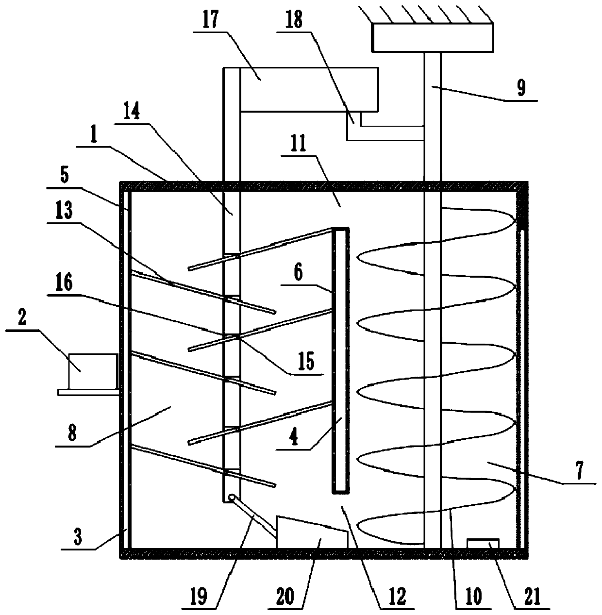
[0038] A kind of sterilization and disinfection equipment for liquid organic fertilizer production, combined with the attached figure 1As shown, it is mainly composed of a first box body 1, a screw shaft 9, a screw blade 10, a partition plate, a rolling screen 13, a swing mechanism, and a steam generating device 2. A feed inlet is installed on the top of the first box body 1 . The partition plate is vertically welded in the first box body 1, the partition plate divides the first box body 1 into the first chamber 7 and the second chamber 8, the upper end of the partition plate and the top of the first box body 1 A first output port 11 is formed between them, and a first valve is installed in the first output port 11; a material return port 12 is formed between the bottom end of the partition plate and the bottom of the first box body 1 . The first chamber 7 is rotationally connected with a screw shaft 9, and the top of the screw shaft 9 passes through the first box body 1 and ...

Embodiment 2

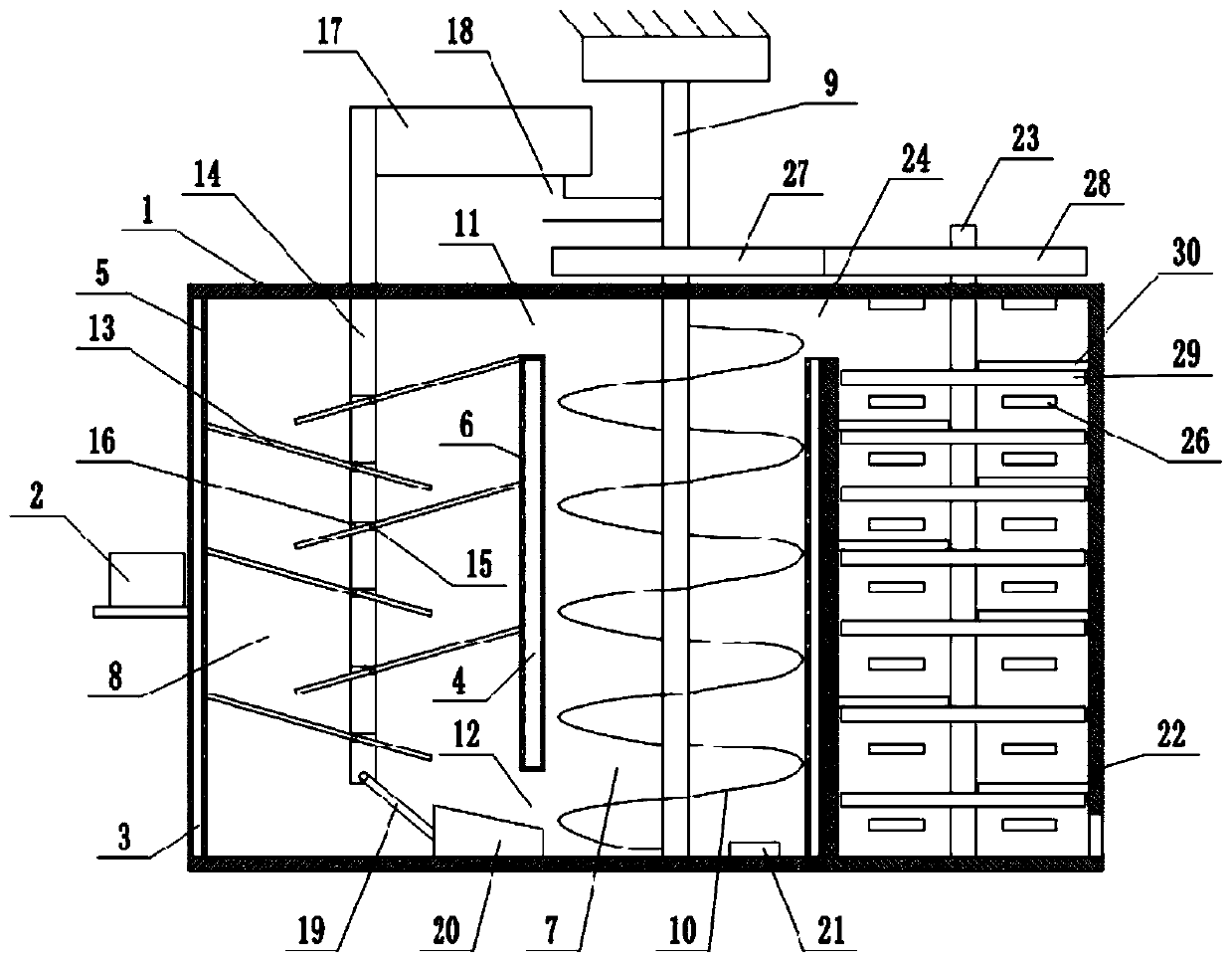
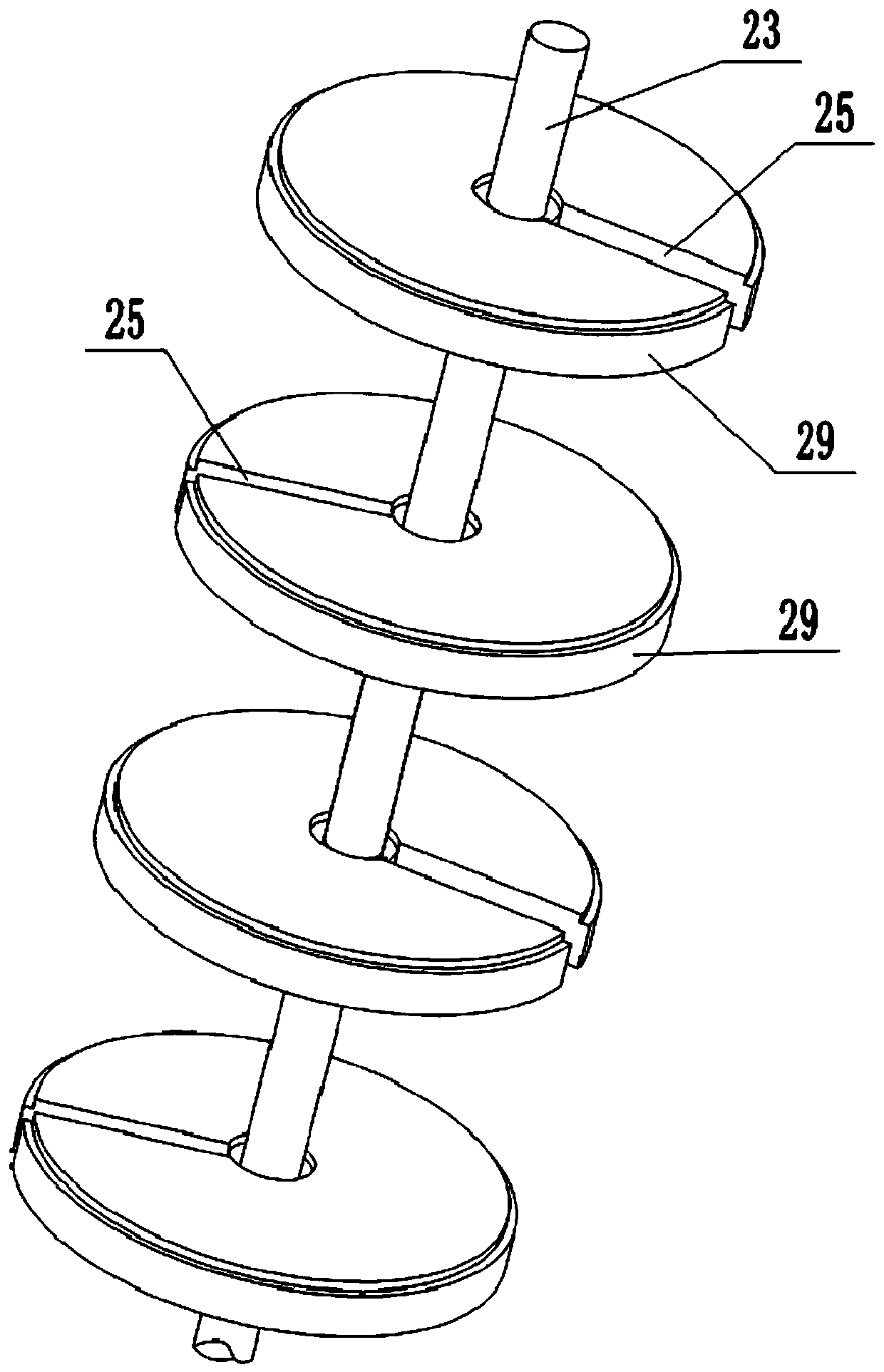
[0049] The difference between this embodiment and Embodiment 1 is that in this embodiment, a second box body 22 is also included, combined with the attached figure 2 , attached image 3 , attached Figure 4 As shown, the second box body 22 is welded on the right outer wall of the first box body 1, and the top of the right side of the first box body 1 is provided with a second output port 24, and the second output port 24 communicates with the top of the second box body 22 , and the second output port 24 is provided with a second valve. The second casing 22 is rotatably connected with a rotating shaft 23, the top of the rotating shaft 23 passes through the second casing 22 and is equipped with a driven gear 28, and the top of the screw shaft 9 passes through the first casing 1 and is equipped with a driving gear 27 , the driven gear 28 meshes with the driving gear 27 . The middle and lower parts of the rotating shaft 23 are detachably connected (specifically plugged) with s...


PUM


Abstract

The invention relates to the technical field of liquid organic fertilizer production, and discloses sterilization and disinfection equipment for liquid organic fertilizer production, which comprises afirst box body, a partition plate, a first chamber, a second chamber, a screw shaft and a screw blade, a plurality of rolling net plates are hinged in the second chamber; a swing mechanism for enabling the rolling net plate to swing up and down is arranged in the second chamber; a mounting plate is arranged at the side part of the first box body; a steam generating device is arranged on the mounting plate; a steam flowing cavity is formed in the side wall of the first box body, the steam flowing cavity is communicated with the steam generating device, a plurality of first spraying openings are formed in the inner wall of the first box body, and the first spraying openings are communicated with the steam flowing cavity. According to the scheme, materials can be dispersed, steam can enter amiddle layer and a bottom layer of the materials more easily, the contact time of the materials and the steam is prolonged, meanwhile, the materials circularly move in the first chamber and the second chamber, the materials make contact with the steam more sufficiently, and the sterilization and disinfection effect of the materials is greatly improved.

Description

technical field [0001] The invention belongs to the technical field of liquid organic fertilizer production. Background technique [0002] In the production process of liquid organic fertilizer, before the material is put into the fermenter for fermentation, the material needs to be sterilized to kill bacteria and germs in the material and improve the fertilizer's fertility. [0003] The existing sterilization and disinfection equipment is to pour all the materials into the box, send steam into the box, and use the stirring device to stir the materials in the box, so as to realize sterilization. [0004] Using this equipment for sterilization, because the materials are piled up together, even with the stirring of the stirring device, the steam is still difficult to penetrate into the bottom and middle layers of the material, and the contact between the steam and the material is not sufficient, resulting in the sterilization effect poor. Contents of the invention [0005]...

Claims


Application Information

Patent Timeline
Patent Type & Authority Applications(China)
IPC IPC(8): A61L2/07A61L2/08A61L2/26
CPCA61L2/07A61L2/08A61L2/26
Inventor 张巍刘存寿叶光忠梁涛罗金
Owner 天府立春(成都)农业发展有限公司
Learn More