Low voltage circuit breaker and method

A low-voltage circuit breaker, low-voltage technology, applied in the direction of circuit, short-circuit test, circuit device, etc., can solve problems such as high cost, and achieve the effect of low-cost, low-ground fault identification

Active Publication Date: 2022-07-15
SIEMENS AG
View PDF8 Cites 0 Cited by
  • Summary
  • Abstract
  • Description
  • Claims
  • Application Information

AI Technical Summary

Problems solved by technology

Such variants as described above are costly

Method used


Image

  • Low voltage circuit breaker and method
  • Low voltage circuit breaker and method
  • Low voltage circuit breaker and method

Examples


Embodiment Construction

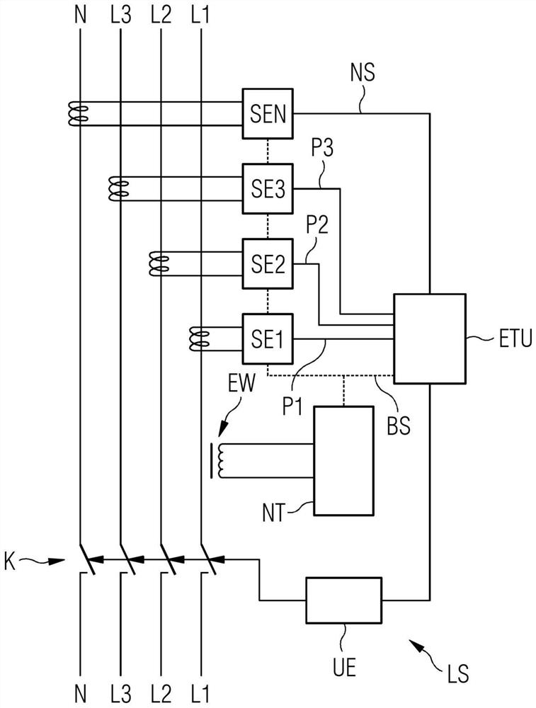
[0049] figure 1 A schematic block diagram of a low voltage circuit breaker LS is shown. figure 1 Electrical conductors L1, L2, L3, N of a low-voltage circuit, for example a three-phase alternating current circuit, are shown, wherein the first conductor L1 forms a first phase with a first phase current P1 and a second conductor L2 forms a second phase current P2 The second phase, the third conductor L3 forms the third phase with the third phase current P3, and the fourth conductor forms the neutral conductor N with the neutral conductor current NS of the three-phase AC circuit. on the basis of figure 1 In the example of (only) the first conductor L1 is connected to the energy converter EW (eg as part of a converter group - especially for all phases L1, L2, L3 and N), such that the full current of the first conductor L1 or At least a part of the current, ie the conductor part current, flows through the primary side of the energy converter EW. Typically, the conductor (in this...


PUM


Abstract

The invention relates to a method for identifying ground faults in a low-voltage three-phase alternating current circuit with a neutral conductor, wherein the first to third phase conductors and the first to fourth simulated currents of the neutral conductor of the three-phase alternating current circuit are determined signal, these analog current signals contain the magnitude of the current or the equivalent of the magnitude of the current, respectively. According to the invention, the analog current signal is time-multiplexed, analog-to-digital converted, thereby presenting a time-multiplexed sequence of first to fourth digital current values ​​presented in first to fourth consecutive time frames, which constitute first to fourth digital current signals. Three of the four digital current signals are interpolated, wherein interpolated current values ​​are determined for the time frame of the uninterpolated digital current signals. The current values ​​for the time frame of the uninterpolated current signal and the interpolated current values ​​for the time frame of the uninterpolated current signal are used to determine the ground fault.

Description

technical field [0001] The invention relates to a low-voltage circuit breaker according to the invention for interrupting a low-voltage circuit, and to a method according to the invention. Background technique [0002] A circuit breaker is a protective device that works like a fuse. The circuit breaker monitors the current flowing through the circuit breaker by means of conductors and, when protection parameters, such as current limit values ​​or current-time interval limit values, are exceeded (i.e. when a current value is present for a specific time interval), interruptions to energy sinks or drains are made. The flow of electrical current or energy to an appliance, this is called a trigger. The set current limit value or current-time interval limit value is the corresponding triggering cause. Interruption is effected, for example, by the contacts of an open circuit breaker. [0003] Especially for low-voltage circuits, low-voltage installations or low-voltage grids, th...

Claims


Application Information

Patent Timeline
Patent Type & Authority Patents(China)
IPC IPC(8): G01R31/52H02H1/00
CPCH02H1/0007H01H83/22H01H71/123H02H3/34H02H3/343H02H3/165H02H3/50H02H1/0092H03M1/12
Inventor A.菲舍尔A.冈斯科雷克
Owner SIEMENS AG
Why Eureka
Try Eureka