Rocket ejection deicing and fire extinguishing system
A technology for ejecting rockets and fire-extinguishing systems, which is applied in the field of rocket-ramjet combined engines, can solve problems such as low efficiency of deicing equipment, and achieve the effects of simple structure, fast deicing speed, and easy maintenance.
- Summary
- Abstract
- Description
- Claims
- Application Information
AI Technical Summary
Problems solved by technology
Method used
Image
Examples
Embodiment 1
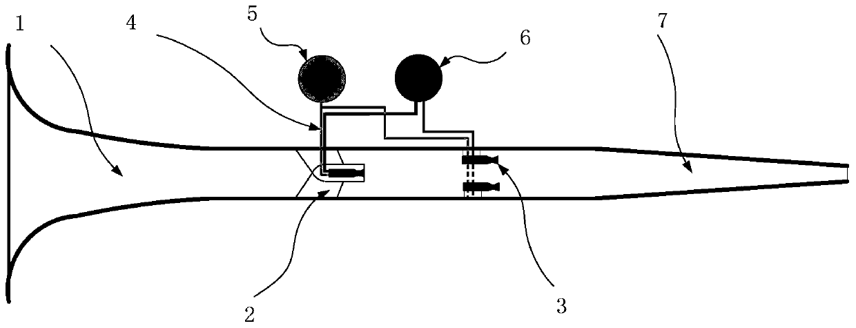
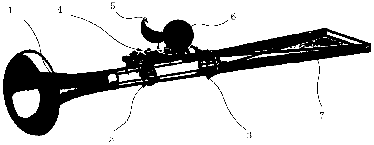
[0022] figure 1 It is a side sectional view of the ejection rocket deicing and fire extinguishing system in Embodiment 1 of the present invention, figure 2 It is a perspective view of the ejection rocket deicing and fire extinguishing system in Embodiment 1 of the present invention; this embodiment takes the layout of a two-stage ejection rocket as an example. Such as figure 1 As shown, the deicing and fire extinguishing system includes a bleed air hood 1 , an ejector rocket combustion chamber, a nozzle 7 , a supply pipeline system 4 , a fuel storage tank 5 and an oxidant storage tank 6 .
[0023] The air-entraining cover 1, the ejection rocket combustion chamber and the nozzle 7 are sequentially connected.
[0024] Two stages of ejector rockets are arranged in the ejector rocket combustion chamber, including center rocket 2 and wall rocket 3, arranged front and back. The "center" and "wall" described in the text refer to the position of the rocket. The central rocket 2 c...
Embodiment 2
[0029] see Figure 4 , in this embodiment, there are multiple combustion chambers connected in parallel, multiple combustion chambers form multiple passages, and each passage is provided with rockets of one or more stages. A plurality of combustion chambers share the bleed hood 1 and the nozzle 7.
Embodiment 3
[0031] see Figure 5 , In this embodiment, the expansion section 8 is connected after the nozzle. The outlet of the expansion section is as large as possible, thereby increasing the contact area between the airflow and the deicing target. If the outlet of the nozzle 7 is circular, the expansion section 8 adopts a circle-to-square expansion section.
[0032] An ejection rocket deicing and fire extinguishing system provided by an embodiment of the present invention innovatively introduces rocket ramjet technology into the field of deicing and fire extinguishing, and realizes a deicing and fire extinguishing equipment with simple structure, high efficiency and easy maintenance. The ejection rocket deicing and fire extinguishing system of the present invention can work under various environmental conditions, and has no requirement on the air in the external environment, and the normal ignition work of the system is not affected by rainy, snowy or windy sand weather.
PUM
 Abstract
Description
Claims
Application Information
 - R&D
- Intellectual Property
- Life Sciences
- Materials
- Tech Scout
- Unparalleled Data Quality
- Higher Quality Content
- 60% Fewer Hallucinations
Browse by: Latest US Patents, China's latest patents, Technical Efficacy Thesaurus, Application Domain, Technology Topic, Popular Technical Reports.
© 2025 PatSnap. All rights reserved.Legal|Privacy policy|Modern Slavery Act Transparency Statement|Sitemap|About US| Contact US: help@patsnap.com


