A new energy charging pile automatic take-up device

A technology of a wire take-up device and a charging pile, which is applied in charging stations, electric vehicles, and electric vehicle charging technology, etc., can solve the problems of low wire take-up stability, spring fatigue, and potential safety hazards.

Active Publication Date: 2021-11-05
ANHUI KECHUANG NEWENERGY TECH CO LTD
View PDF0 Cites 0 Cited by
  • Summary
  • Abstract
  • Description
  • Claims
  • Application Information

AI Technical Summary

Problems solved by technology

[0002] The new energy charging pile is a device that can be installed in public areas or parking lots in residential areas to provide charging for different types of electric vehicles. During the use of existing charging piles, people often need to drag long charging cables to use them. , the wear and tear of the charging cable dragging the ground can easily cause damage to the charging cable, and it is also easy to be damaged by the electric vehicle rolling and collision. At the same time, most of the existing charging piles are manually taken up, which makes the take-up stability not high and the efficiency low , it is not convenient for people to use, and the charging cable is exposed outside the charging pile, which is likely to cause the aging of the charging cable insulation layer, which brings certain safety hazards. To solve this problem, in the prior art, an automatic wire take-up device can be used Automatic take-up, the automatic take-up device can automatically take back the charging cable in a winding way by using the energy storage and release of the built-in rewinding spring, but because the charging cable of the charging pile is generally a thicker and heavier line It is not easy to wind the cable, and it is easy to damage the insulation layer under long-term excessive bending, and the core core inside will be broken, which will affect the normal use or service life of the charging cable. On the other hand, the automatic take-up The rewinding spring in the rewinder is the main component. Repeated energy storage and release during work will easily cause spring fatigue, which will affect the normal use or service life of the automatic reel.

Method used


Image

  • A new energy charging pile automatic take-up device
  • A new energy charging pile automatic take-up device
  • A new energy charging pile automatic take-up device

Examples


Embodiment Construction

[0028] In order to make the objects, technical solutions, and advantages of the present invention, the present invention will be further described in detail below with reference to the accompanying drawings.

[0029] It should be noted that all expressions using "first" and "second" in the embodiments of the present invention are in order to distinguish between two identical names of different entities or non-identical parameters, visible "first" "second" For the convenience of expression, it is not understood to be limited to the embodiment of the present invention, and the subsequent embodiment will not be described herein.

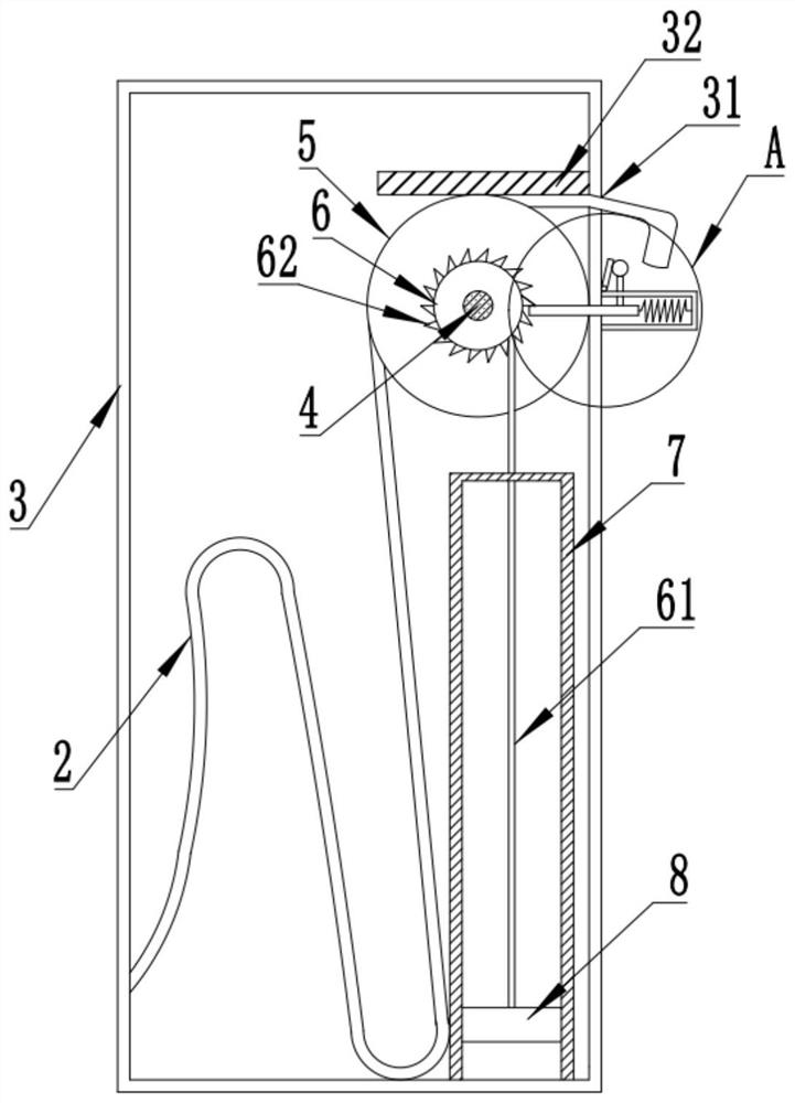
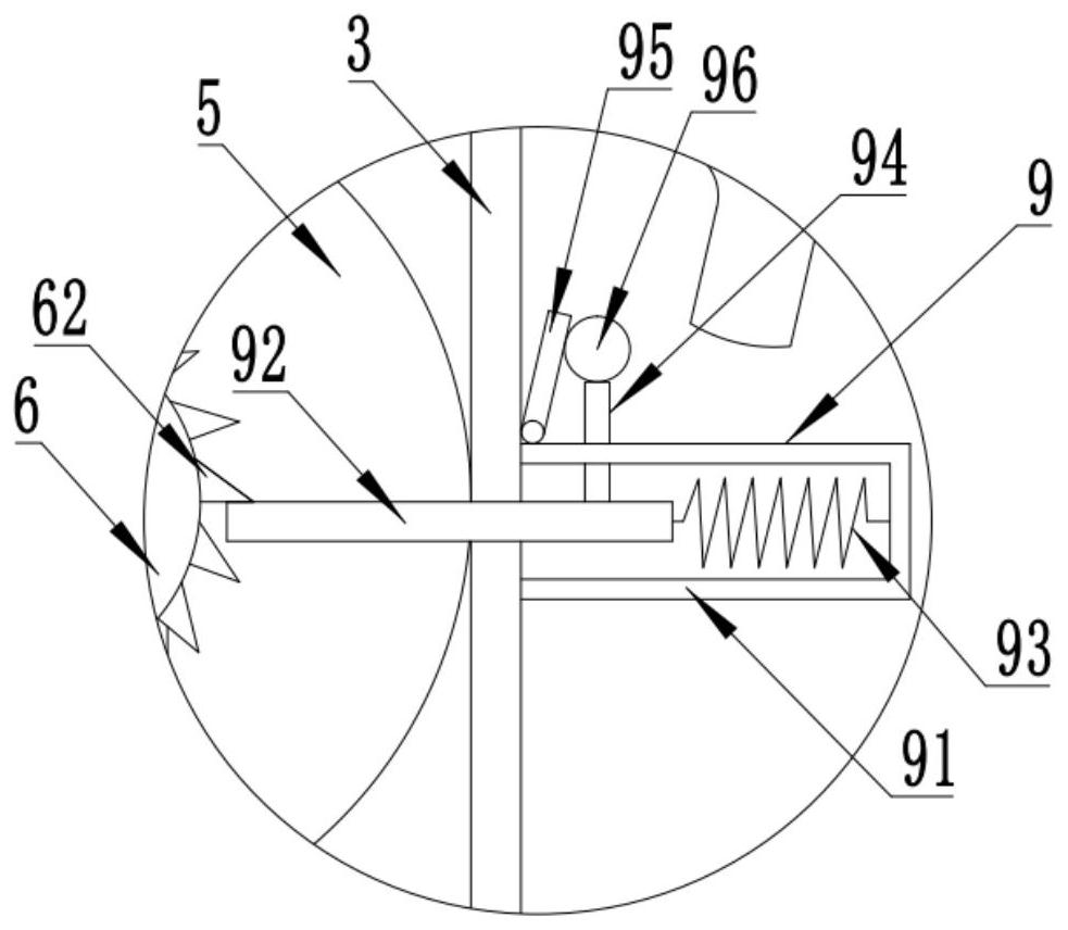
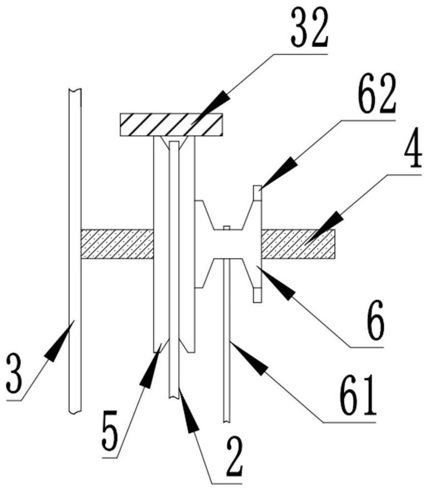
[0030] A new energy charging pile automatic tapping device, such as Figure 1 to 4 As shown, including the charging pile body 1, the charging pile body 1 is connected to the charging cable 2, and the charging pile body 1 is fixed to the retaining chamber 3, and the wire chamber 3 is provided, and the line hole 31 is provided, the upper end of the harrse line...


PUM


Abstract

The invention discloses an automatic wire take-up device for a new energy charging pile, which includes a charging pile body, a charging cable connected to the charging pile body, a wire take-up chamber fixed on the side of the charging pile body, the charging cable introduced into the wire take-up chamber, and Run through the outlet hole along the upper end of the guide wheel, the guide wheel is coaxially connected with a wire rope reel, the wire rope is wound on the wire rope reel, the other end of the wire rope is connected to the upper end of the piston block in the piston cylinder, when the charging cable is pulled out for charging, it can Drive the wire wheel to rotate to drive the wire rope reel to rotate synchronously, so that the wire rope pulls the piston block to move upward. At the same time, a self-locking device is provided to limit the piston block to only move upward in one direction. Unlocking the self-locking device can stop the restriction on the movement of the piston block. The piston block moves downward under the action of gravity, which can drive the wire rope reel to rotate, so as to drive the wire wheel to rotate, so as to retract the charging cable into the wire take-up cavity to realize automatic charging. Take-up function.

Description

Technical field [0001] The present invention relates to the field of new energy charging piles, in particular to a new energy charging pile automatic collection device. Background technique [0002] New energy charging piles are a device that can be installed in public areas or cell parking available. Existing charging piles often need to be dragged for long charging cables during use. The charging cable is dragged and easy to cause damage to the charging cable. It is also easy to be damaged by electric vehicles. At the same time, most of the existing charging piles are transmitted by manual construction, so that the removal line is not high and the efficiency is low. It is not convenient for people's use, and the charging cable is exposed to the outside of the charging pile, which is easy to cause aging of the charging cable insulation, thereby bringing certain safety hazards, for this problem, in the prior art, can be implemented using automatic hub implementation Automatic tap...

Claims


Application Information

Patent Timeline
Patent Type & Authority Patents(China)
IPC IPC(8): B65H75/48B60L53/18
CPCB65H75/48B65H2701/34B60L53/18Y02T10/70Y02T10/7072Y02T90/14
Inventor 吴浩
Owner ANHUI KECHUANG NEWENERGY TECH CO LTD
Why Eureka
Try Eureka