


Quick Research
Generate reliable direction feasibility study reports for your R&D in just a few steps.

Technical Q&A
Discover and master advanced knowledge NOW. Basics, ideas, possibilities, all at once.

Find Solutions
As an expert in R&D theories, this can generate solutions to your technical problems instantly.

Evaluate Feasibility
Analyze your overall solution with one click, know your potential R&D risks in advance.

Monitor Landscape
Get weekly tech updates, stay abreast of the latest tech innovations and key insights.
Automatic-control take-up and pay-off device for spinning
A wire take-up and pay-off device, textile technology, which is applied in the field of automatic control of the take-up and pay-off device for textiles, and can solve problems such as thread accumulation and unstable thread tension
- Summary
- Abstract
- Description
- Claims
- Application Information
AI Technical Summary
Problems solved by technology
Method used
Image

Examples
Embodiment 1
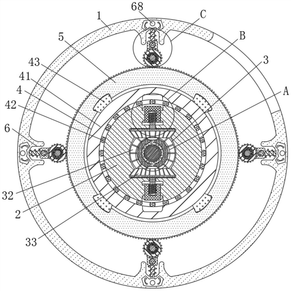
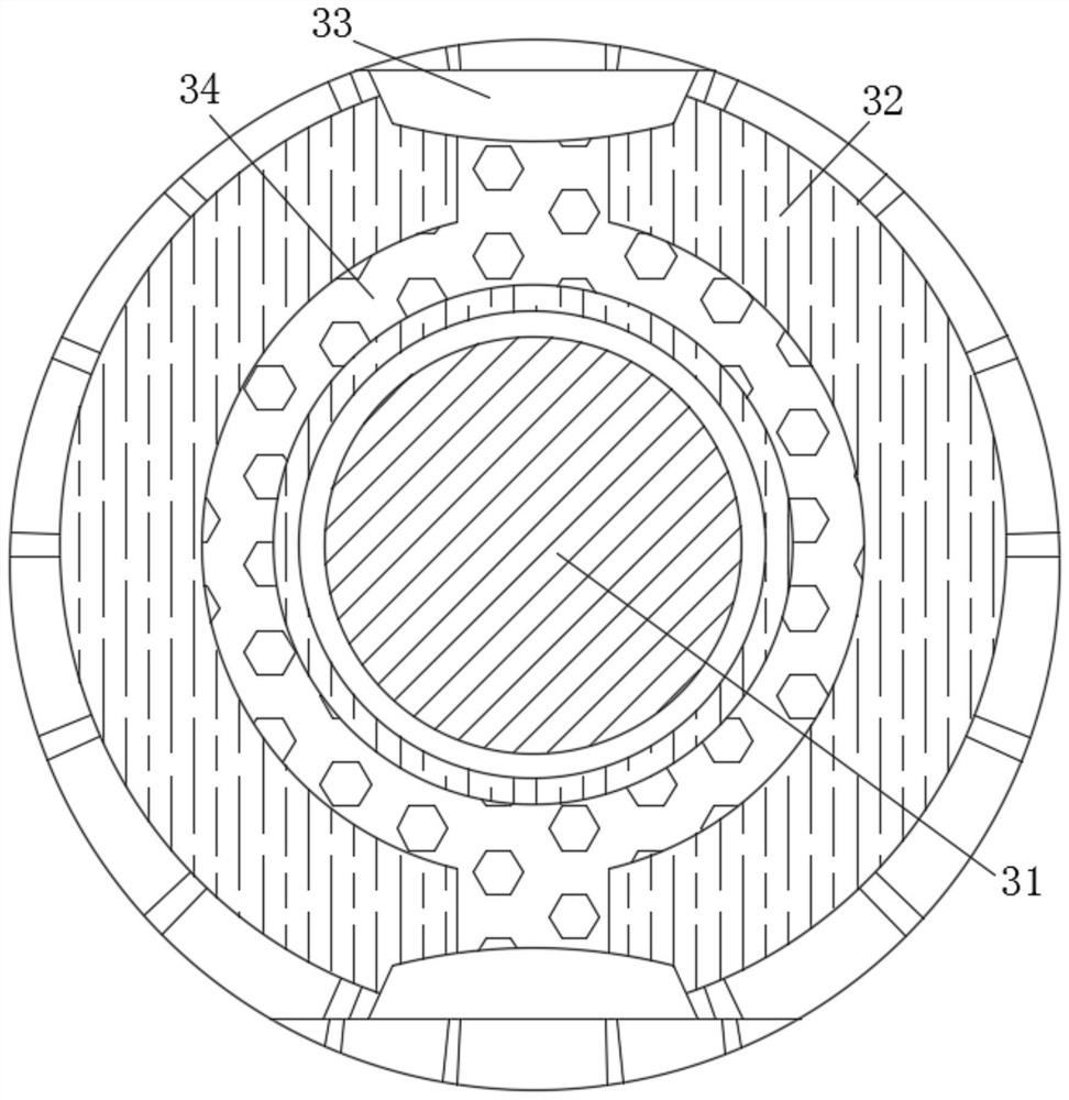
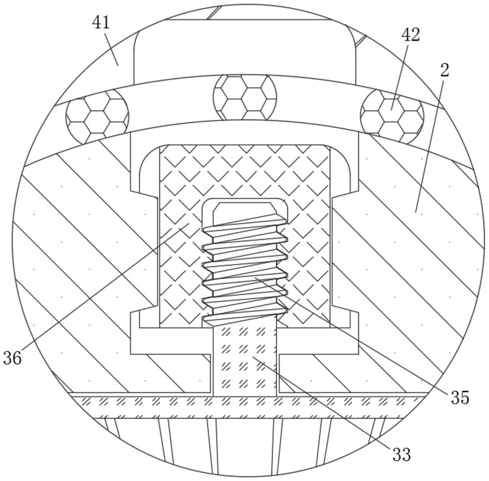
[0026] see Figure 1-3 , an automatic controlled take-up and pay-off device for textiles, including a housing 1, and also includes a main shaft 2, a clamping mechanism 3, a retracting mechanism 4, a wire wheel 5, and a pulling mechanism 6, and the main shaft 2 is fixedly connected to the shell. Inside the body 1, the clamping mechanism 3 is movably connected to the inside of the main shaft 2. The clamping mechanism 3 includes an adjustment shaft 31, a gear one 32, a gear two 33, a support rod 34, a threaded rod 35, a clamping block 36, and the adjustment shaft 31 is movably connected inside the main shaft 2, gear 1 32 is fixedly connected inside the main shaft 2 and is fixedly connected with the adjustment shaft 31, gear 2 33 is movably connected inside the main shaft 2 and is movably connected with gear 1 32, and the support rod 34 is movably connected to the inner side of the second gear 33, the threaded rod 35 is fixedly connected to the outer side of the second gear 33, an...
Embodiment 2
[0031] see Figure 1-4 , an automatic controlled take-up and pay-off device for textiles, including a housing 1, and also includes a main shaft 2, a clamping mechanism 3, a retracting mechanism 4, a wire wheel 5, and a pulling mechanism 6, and the main shaft 2 is fixedly connected to the shell. Inside the body 1, the clamping mechanism 3 is movably connected to the inside of the main shaft 2. The clamping mechanism 3 includes an adjustment shaft 31, a gear one 32, a gear two 33, a support rod 34, a threaded rod 35, a clamping block 36, and the adjustment shaft 31 is movably connected inside the main shaft 2, gear 1 32 is fixedly connected inside the main shaft 2 and is fixedly connected with the adjustment shaft 31, gear 2 33 is movably connected inside the main shaft 2 and is movably connected with gear 1 32, and the support rod 34 is movably connected to the inner side of the second gear 33, the threaded rod 35 is fixedly connected to the outer side of the second gear 33, an...
PUM
 Abstract
Description
Claims
Application Information
 - R&D Engineer
- R&D Manager
- IP Professional
- Industry Leading Data Capabilities
- Powerful AI technology
- Patent DNA Extraction
Browse by: Latest US Patents, China's latest patents, Technical Efficacy Thesaurus, Application Domain, Technology Topic, Popular Technical Reports.
© 2024 PatSnap. All rights reserved.Legal|Privacy policy|Modern Slavery Act Transparency Statement|Sitemap|About US| Contact US: help@patsnap.com