Manual punching device

A punching device and punching technology, applied in wood stamping, punching machines, metal processing, etc., can solve the problems of high cost, difficulty in meeting small-scale fast punching processing, and low processing efficiency of drilling machines, and achieve low cost and structural Simple, wide-ranging effects

Inactive Publication Date: 2020-03-17
HUNAN NONGGUANG AGRI EQUIP CO LTD
View PDF5 Cites 2 Cited by
  • Summary
  • Abstract
  • Description
  • Claims
  • Application Information

AI Technical Summary

Problems solved by technology

At present, the industry generally adopts drilling, punching, or laser overall cutting for medium-hole processing; however, the processing efficiency of drilling is low, while punch

Method used


Image

  • Manual punching device
  • Manual punching device

Examples


Embodiment 1

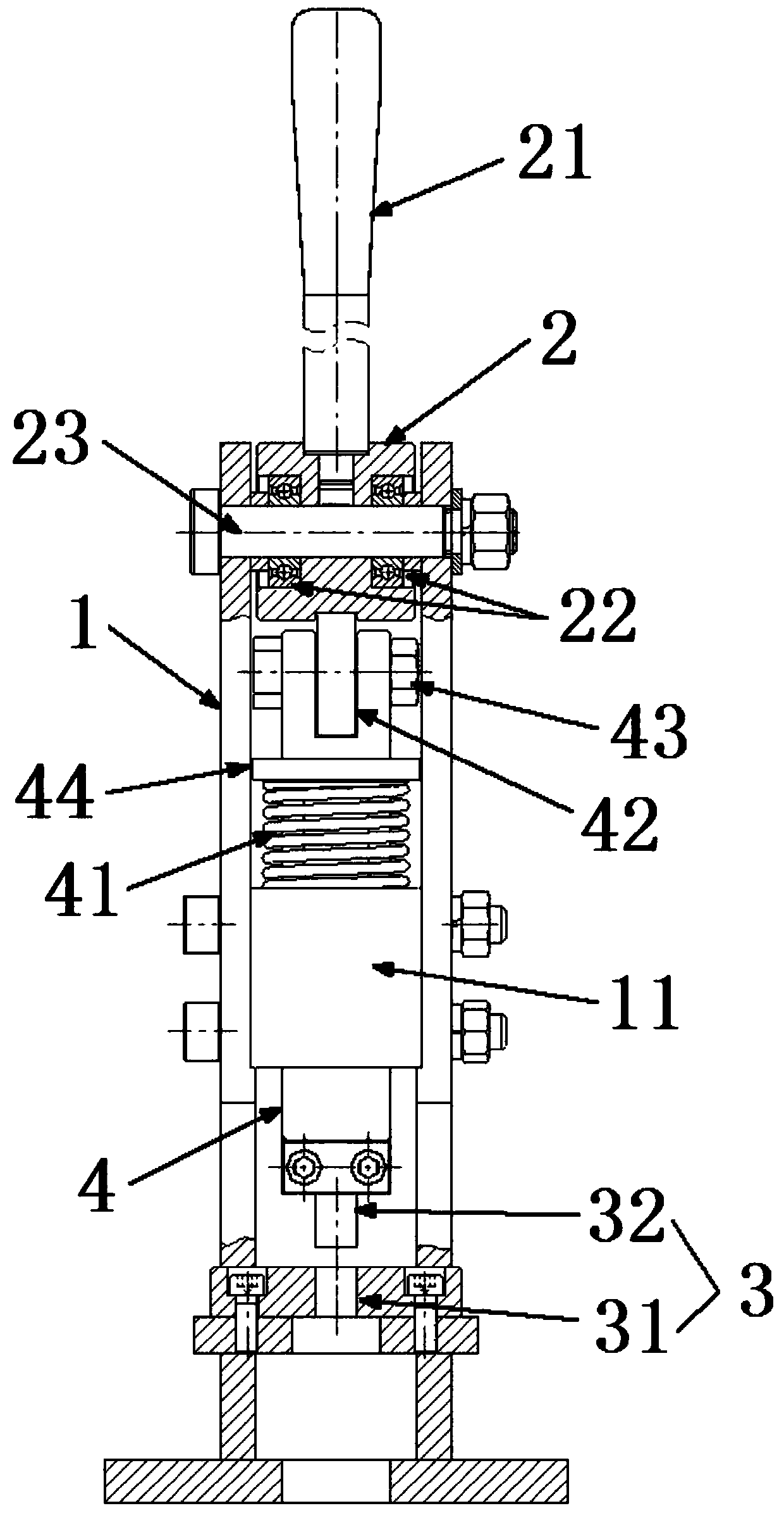
[0057] A manual punching device, comprising:

[0058] Rack 1;

[0059] An eccentric wheel 2 rotatably arranged on the frame 1;

[0060] The die 31 of the punching die 3 arranged at the bottom of the frame 1;

[0061] A telescopic rod 4 arranged in the frame 1, one end of the telescopic rod 4 is provided with a punch 32 of a punching die 3, and the other end is matched with the eccentric wheel 2;

[0062] The telescopic rod 4 is also provided with a return elastic member 41 , and the return elastic member 41 is respectively connected to the telescopic rod 4 and the frame 1 .

[0063] One end of the telescopic rod 4 close to the eccentric wheel 2 is also provided with a first bearing 42 and a first locking rod 43, and the first bearing 42 is fixedly sleeved on the first locking rod 43. The first locking rod 43 is fixedly connected with the telescopic rod 4 . The eccentric wheel 2 is provided with a groove matching the first bearing 42 .

[0064] The eccentric wheel 2 is als...


PUM


Abstract

The invention discloses a manual punching device. The manual punching device comprises a rack (1); an eccentric wheel (2) which is rotatably arranged on the rack (1); a female die (31) of a punching die (3) which is arranged at the bottom of the rack (1); a telescopic rod (4) which is arranged in the rack (1), wherein a male die (32) of the punching die (3) is arranged at one end of the telescopicrod (4), and the other end of the telescopic rod (4) is matched with the eccentric wheel (2); the telescopic rod (4) is further provided with a return elastic part (41), and the return elastic part (41) is connected with the telescopic rod (4) and the rack (1). The manual punching device is simple in structure, small, exquisite, flexible, convenient to use, low in cost, high in efficiency, capable of being moved to any position to be used, capable of adapting to various working environments, capable of meeting various hole machining requirements for punching, chambering, hole repairing and the like and wide in application range.

Description

technical field [0001] The present application relates to the technical field of machining equipment, in particular to a manual punching device. Background technique [0002] Punching refers to punching various graphics on steel plates, leather, cloth, wood and other materials to meet different processing or assembly requirements. At present, the industry generally adopts drilling, punching, or laser overall cutting for medium-hole processing; however, the processing efficiency of drilling is low, while punching and laser processing are highly efficient and suitable for large-scale processing, but the cost is high, and it is difficult to meet small-scale rapid punching. processing needs. Contents of the invention [0003] In order to solve the above technical problems, the purpose of the present invention is to provide a manual punching device; the manual punching device provided by the application has a simple structure, small and flexible, easy to use, low cost and high...

Claims


Application Information

Patent Timeline
IPC IPC(8): B30B1/26B30B15/02B30B15/04B21D28/24B26F1/02B27M1/04
CPCB21D28/24B26F1/02B27M1/04B30B1/26B30B15/02B30B15/04
Inventor 陈兵胡心灵李铁辉
Owner HUNAN NONGGUANG AGRI EQUIP CO LTD
Why Eureka
Try Eureka