
CT scanning frame and CT scanning device

A scanning frame and mounting hole technology, which is used in computer tomography scanners, medical science, instruments used for radiological diagnosis, etc., can solve the problem that the CT scanning frame is difficult to meet at the same time, and achieve the effect of saving time and improving replacement efficiency.

Pending Publication Date: 2020-03-17
SAINUO WEISHENG SCI & TECH BEIJING
View PDF0 Cites 2 Cited by
  • Summary
  • Abstract
  • Description
  • Claims
  • Application Information

AI Technical Summary

Problems solved by technology

[0004] The purpose of the present invention is to solve the problem that the existing CT scanning frame is difficult to meet the needs of fixed CT, mobile CT and suspended CT at the same time

Method used


Image

  • CT scanning frame and CT scanning device
  • CT scanning frame and CT scanning device
  • CT scanning frame and CT scanning device

Examples


Embodiment 1

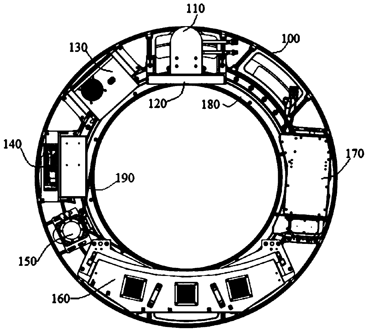
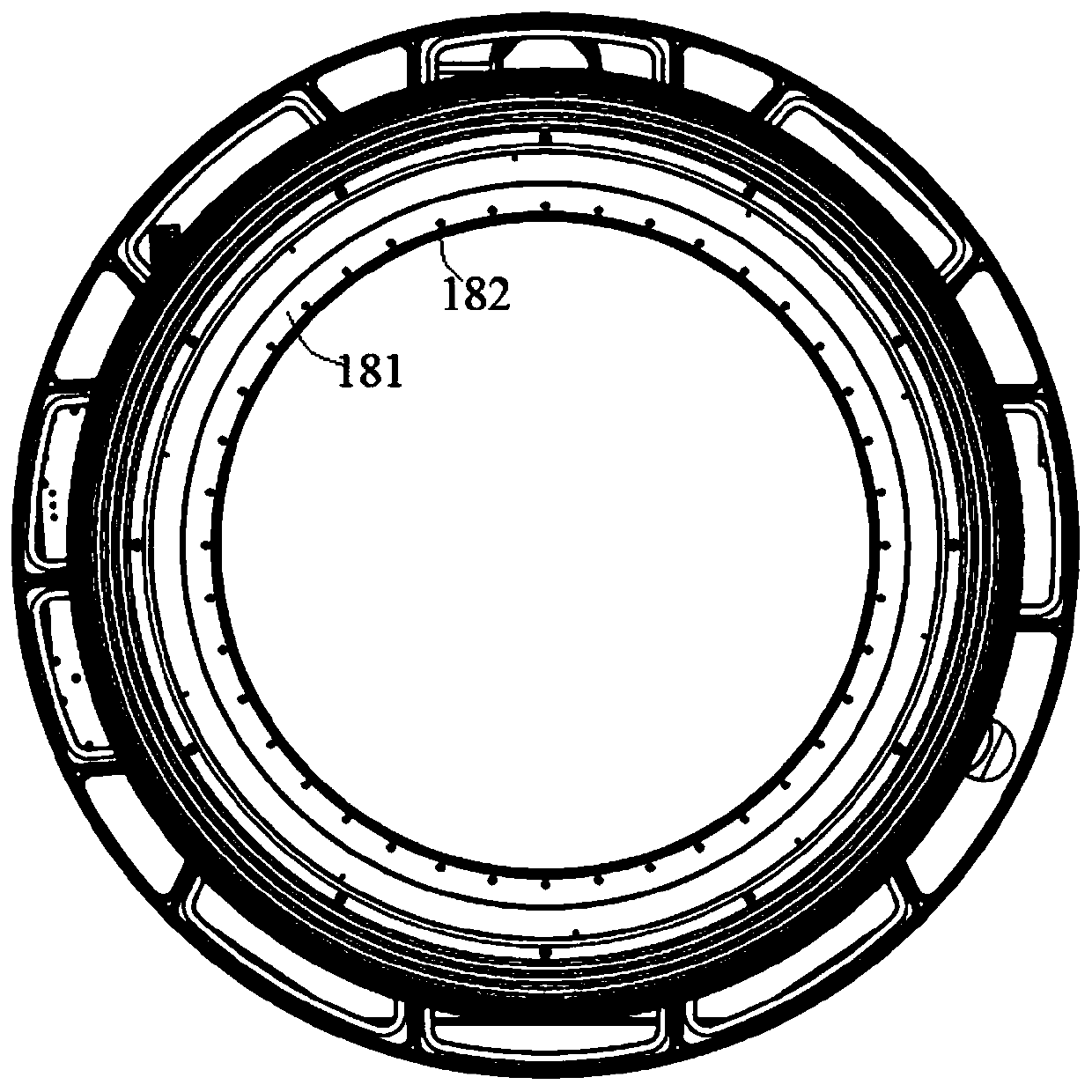
[0034] Refer to attached Figure 1-5 , a CT scanning frame of the present embodiment includes a scanning frame body 100 and a transmission pulley 180 arranged in the scanning frame body 100, the transmission pulley 180 is connected with a main rotation bearing 181, and the transmission pulley 180 and the main rotation bearing 181 is arranged concentrically, and the driving pulley 180 and the main rotating bearing 181 rotate synchronously. The inner ring of the main rotating bearing 181 is provided with mounting holes 182 distributed in the circumferential direction, and the mounting holes 182 are used to connect the fixing frame. By dismounting the mounting holes 182 and the fixing frame, the scanning frame body 100 can be easily connected with the fixing frame. The assembly and replacement improves the replacement efficiency of the scanning frame body 100 and saves time. The fixing frame is provided with a mounting ring, and the mounting ring is provided with a threaded hole...

Embodiment 2

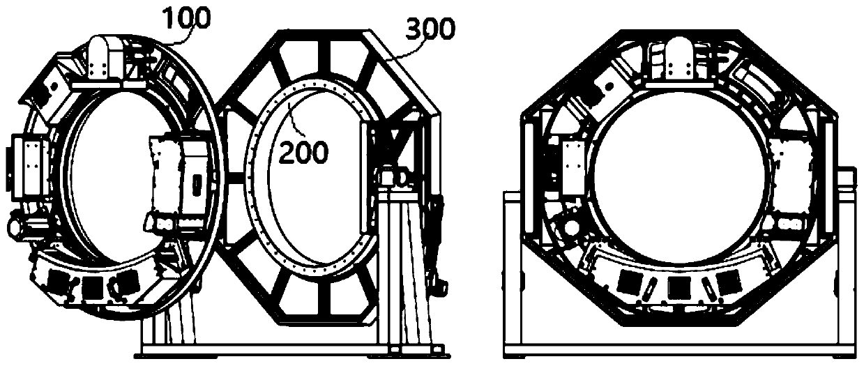
[0042] A CT scanning device, comprising the above-mentioned CT scanning frame and a fixed frame, the fixed frame is a fixed CT fixed frame 300 or a mobile CT fixed frame 400 or a suspended CT fixed frame 500, and the fixed CT fixed frame The frame 300, the mobile CT fixed frame 400 and the suspended CT fixed frame 500 are all equipped with a mounting ring 200, the size of the mounting ring 200 is adapted to the size of the inner ring of the main rotating bearing 181, and the mounting ring 200 A threaded hole matching the mounting hole 182 is provided on the top, and the mounting hole 182 and the threaded hole are connected by screws.

[0043] The fixed CT fixer 300, the mobile CT fixer 400 and the suspended CT fixer 500 are all provided with mounting rings 200 of the same size. It only needs to be disassembled and replaced on the fixed frame, so as to realize the function that one scanning frame body 100 can adapt to different types of fixed frames.


PUM


Abstract

The invention discloses a CT scanning frame and a CT scanning device. The scanning frame comprises a scanning frame main body and a transmission belt wheel arranged in the scanning frame main body, the transmission belt wheel is connected to a main rotating bearing, circumferentially distributed mounting holes are formed in an inner ring of the main rotating bearing, the mounting hole is used forconnecting a fixing frame, through dismounting the mounting holes and the fixing frame, the scanning frame main body can be conveniently assembled with the fixing frame and replaced, the CT scanning device comprises the CT scanning frame and the fixing frame, the fixing frame is a fixed CT fixing frame or a movable CT fixing frame or a suspension type CT fixing frame, the fixed CT fixing frame, the movable CT fixing frame and the suspension type CT fixing frame are each provided with an installation ring, the installation ring is provided with a threaded hole matched with the installation hole, and when the CT scanning frame needs to be installed, the CT scanning frame can be detached from the fixing frames of different types to be replaced, and then the function that one CT scanning frameis matched with the fixing frames of different types can be achieved.

Description

technical field [0001] The invention belongs to the technical field of medical equipment, in particular to a CT scanning frame and a CT scanning device. Background technique [0002] A traditional CT scanning system consists of a scanning frame (containing a rotatable X-ray source and an X-ray detector inside), a scanning table (containing a bed board that can move horizontally to support the patient being scanned), an operation console (providing a user interface , receiving and saving scanning data, reconstructing and displaying CT tomographic images), and some auxiliary systems. However, the current CT scanning frames are divided into fixed CT scanning frames, mobile CT scanning frames and suspended CT scanning frames. Among them, the fixed CT scanning frame has a large overall appearance size and the weight of the whole machine is very heavy, while the mobile CT and hanging CT scanning frames The size is relatively small, and the weight of the whole machine is relativel...

Claims


Application Information

Patent Timeline
Patent Type & Authority Applications(China)
IPC IPC(8): A61B6/00A61B6/03
CPCA61B6/035A61B6/4435A61B6/4488
Inventor 王君涛任敬轶
Owner SAINUO WEISHENG SCI & TECH BEIJING
Learn More