
Umbrella rod device, umbrella rod transmission assembly thereof and electric umbrella

A technology of transmission components and electric umbrellas, applied in umbrellas, clothing, walking sticks, etc., can solve the problems of complex structure of transmission components of umbrella poles

Pending Publication Date: 2020-03-17
吕孙宝
View PDF0 Cites 1 Cited by
  • Summary
  • Abstract
  • Description
  • Claims
  • Application Information

AI Technical Summary

Problems solved by technology

Among them, the umbrella pole device usually extends or shortens the umbrella pole through the umbrella pole transmission assembly, but the traditional umbrella pole transmission assembly has a complicated structure

Method used


Image

  • Umbrella rod device, umbrella rod transmission assembly thereof and electric umbrella
  • Umbrella rod device, umbrella rod transmission assembly thereof and electric umbrella
  • Umbrella rod device, umbrella rod transmission assembly thereof and electric umbrella

Examples


Embodiment Construction

[0056]The technical solutions in the embodiments of the present invention will be clearly and completely described below with reference to the accompanying drawings in the embodiments of the present invention. Obviously, the described embodiments are only a part of the embodiments of the present invention, not all of the embodiments. Based on the embodiments of the present invention, all other embodiments obtained by those of ordinary skill in the art without creative efforts shall fall within the protection scope of the present invention.

[0057] It should be noted that if there are directional indications (such as up, down, left, right, front, back, etc.) involved in the embodiments of the present invention, the directional indications are only used to explain a certain posture (as shown in the accompanying drawings). If the specific posture changes, the directional indication also changes accordingly.

[0058] In addition, if there are descriptions involving "first", "seco...


PUM


Abstract

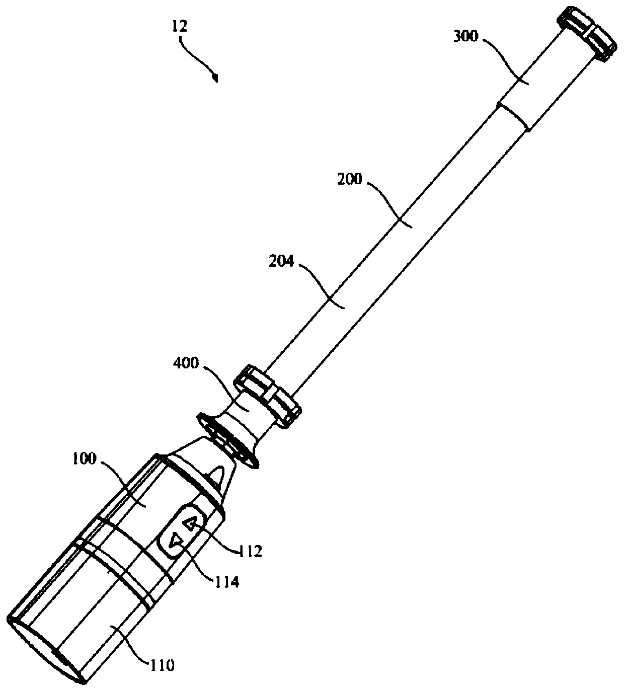
The invention discloses an umbrella rod device, an umbrella rod transmission assembly thereof and an electric umbrella, the umbrella rod transmission assembly comprises a first rod structure, a secondrod structure and a spring, and the first rod structure comprises a first rod body and a rotation stopping part with a large outer diameter; the second rod structure comprises a second rod body and apressure spring part, the second rod body is inserted into the first rod structure, the pressure spring part is located outside the end, away from the first rod body, of the rotation stopping part, the end face, close to the second rod body, of the pressure spring part is a pressure spring face, and the pressure spring part is provided with a spring guide passage; the spring sleeves the first rodstructure, and at least part of the spring ring of the spring is arranged in the spring guide passage; when the second rod structure and the first rod structure rotate relatively, the spring compressed on the side, close to the second rod body, of the compressed spring face can be released, the spring stretches out from the end, away from the rotation stopping part, of the compressed spring partand applies force to the middle rod, the multiple sleeves of the middle rod are pulled open to form a long rod connected end to end, and the spring can be compressed to withdraw the force applied to the middle rod. The umbrella rod transmission assembly is simple in structure.

Description

technical field [0001] The invention relates to the field of electric umbrellas, in particular to an umbrella pole device, an umbrella pole transmission assembly thereof, and an electric umbrella. Background technique [0002] After the folding umbrella is folded, the length is small, and it is very easy to carry and store, so it is deeply loved by the majority of users. However, the traditional folding umbrella usually requires the user to use both hands to open or close it. When the user holds an object in one hand and the umbrella in the other, it is not convenient to open or close the folding umbrella conveniently and quickly. In order to open or close folding umbrellas more conveniently and quickly, people have designed electric umbrellas. An electric umbrella usually includes an umbrella pole device and an umbrella rib device, and the umbrella rib device is arranged on the umbrella pole device. When the electric umbrella is opened, the umbrella rod device needs to be...

Claims


Application Information

Patent Timeline
Patent Type & Authority Applications(China)
IPC IPC(8): A45B19/04A45B19/10A45B25/02A45B25/14
CPCA45B19/04A45B19/10A45B25/02A45B25/143
Inventor 吕孙宝
Owner 吕孙宝
Learn More