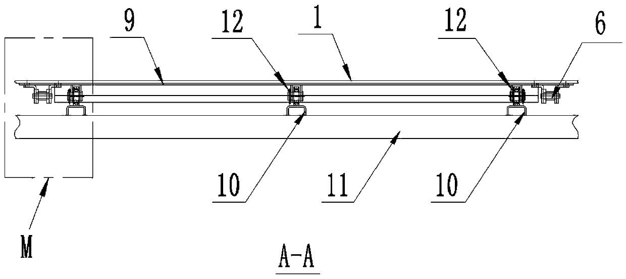
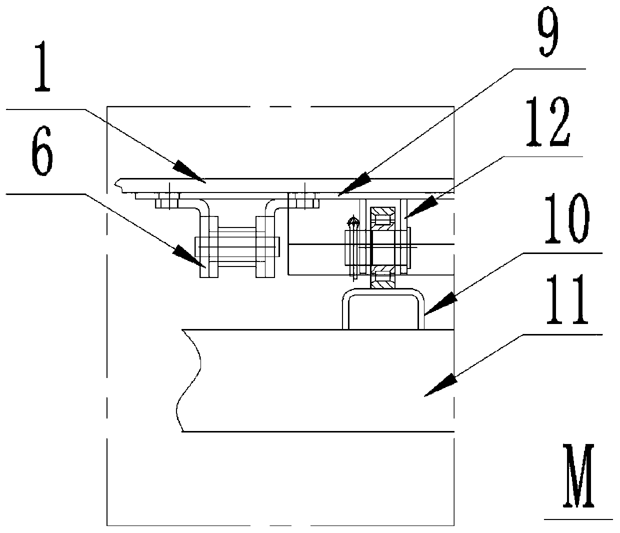
Vehicle-mounted conveying belt structure
A technology for conveyor belts and conveyor chains, which is applied in the field of conveyor belts and vehicle-mounted conveyor belt structures. It can solve the problems of uncommon components, wear of conveyor belts, and chain wear, and achieve fewer models, lower manufacturing costs, and longer service life. Effect
- Summary
- Abstract
- Description
- Claims
- Application Information
AI Technical Summary
Problems solved by technology
Method used
Image
Examples
Embodiment 1
[0032] Such as Figure 1 to Figure 3 As shown, a vehicle-mounted conveyor belt structure provided in this embodiment includes a conveyor belt 1, a first conveyor belt guide 2 is pierced at one end of the conveyor belt 1, and a second conveyor belt guide 2 is pierced at the other end of the conveyor belt 1. Conveyor belt guide device 3; the first conveyor belt guide device 2 and the second conveyor belt guide device 3 are respectively pressed and fitted to the inner surfaces of both ends of the conveyor belt 1, and are used to tension and pull the conveyor belt 1 forward, so that the conveyor belt 1 The linear speed of the conveyor chain beam 9 corresponding to the conveyor belt 1 running at both ends of the conveyor belt 1 is consistent, thereby avoiding the relative movement of the conveyor chain beam 9 and the conveyor belt 1 due to inconsistent linear speeds at both ends. The phenomenon of the conveyor belt makes the service life of the conveyor belt 1 be extended;
[0033...
Embodiment 2
[0044] The difference between this embodiment and embodiment 1 is: as Figure 4 As shown, a third conveyor belt guide 4 and a conveyor belt tensioning device 5 are also provided at one end of the conveyor belt 1 passing through the second conveyor belt guide 3;
[0045] Wherein, the third conveyor belt guiding device 4 is supported on the outside of the bottom of the conveyor belt 1, and is tightly fitted with the outer surface of the bottom of the conveyor belt 1, and the conveyor belt tensioner 5 is supported on the inside of the bottom of the conveyor belt 1, and is connected to the conveyor belt 1 bottom. The inner surfaces of the lower part of the band 1 are pressed together tightly.
[0046] Specifically, in this embodiment, the third conveyor belt guiding device 4 is a guide roller, and the conveyor belt tensioning device 5 is a tension roller.
Embodiment 3
[0048] The difference between this embodiment and embodiment 2 is: as Figure 5 with Image 6 As shown, a first guide transmission sprocket 14 is also respectively provided at both ends of the first conveyor belt guide 2, and a second guide transmission sprocket 15 is respectively provided on one side of each driving sprocket 7, Each first guide drive sprocket 14 is correspondingly engaged and drive-connected with a second guide drive sprocket 15 through a conveyor belt guide drive chain 13 .
[0049] This embodiment is mainly used to solve the further improvement measures provided when the remaining goods to be unloaded in the compartment are less and lighter in weight, because when the goods are lighter, the conveyor chain beam 9 and the conveyor belt 1 at this time The frictional force is small, not enough to drive the conveyor belt 1 to rotate. At this time, the conveyor belt 1 will slip, which will affect the unloading efficiency. At the same time, the conveyor chain bea...
PUM
 Abstract
Description
Claims
Application Information
 - Generate Ideas
- Intellectual Property
- Life Sciences
- Materials
- Tech Scout
- Unparalleled Data Quality
- Higher Quality Content
- 60% Fewer Hallucinations
Browse by: Latest US Patents, China's latest patents, Technical Efficacy Thesaurus, Application Domain, Technology Topic, Popular Technical Reports.
© 2025 PatSnap. All rights reserved.Legal|Privacy policy|Modern Slavery Act Transparency Statement|Sitemap|About US| Contact US: help@patsnap.com


