Image recovery method and coding end
An image restoration and image reconstruction technology, applied in the field of video coding and decoding, can solve the problems of difficulty in ensuring image quality, inability to guarantee image quality, and large image code size, so as to reduce network packet loss, improve anti-packet loss capability, and improve image quality. The effect of quality and fluidity
- Summary
- Abstract
- Description
- Claims
- Application Information
AI Technical Summary
Problems solved by technology
Method used
Image

Examples
Embodiment 1
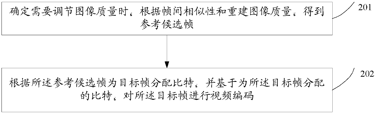
[0027] figure 2 It is a schematic flowchart of the image restoration method provided by Embodiment 1 of the present invention. Such as figure 2 As shown, the image recovery method includes:
[0028] Step 201, when it is determined that image quality needs to be adjusted, obtain reference candidate frames according to inter-frame similarity and reconstructed image quality;
[0029] Step 202: Allocate bits for a target frame according to the reference candidate frame, and perform video encoding on the target frame based on the bits allocated for the target frame.
[0030] Wherein, the determination needs to adjust the image quality, including:
[0031] Determining the similarity measure between frames and reconstructed image quality;
[0032] According to the determined inter-frame similarity measure, inter-frame similarity measure threshold, reconstructed image quality, reconstructed image quality threshold, and decoding feedback information, it is determined that the ima...
Embodiment 2
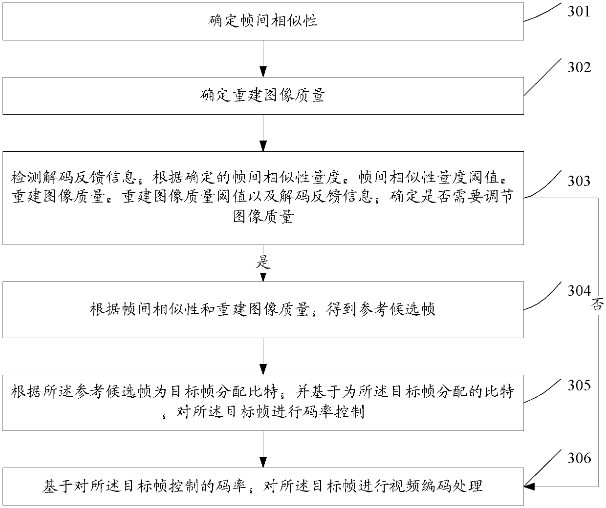
[0049] image 3 It is a schematic flowchart of the image restoration method provided by Embodiment 2 of the present invention. Such as image 3 As shown, the image recovery method includes:
[0050] Step 301, determine the similarity between frames;
[0051] Wherein, determining the inter-frame similarity is specifically determining an inter-frame similarity measure. When determining the inter-frame similarity measure, you can choose motion vector or pixel-based motion complexity to determine the inter-frame similarity measure; the inter-frame similarity measure threshold can be set as needed, and the inter-frame similarity measure threshold is used to set The level of similarity between frames;
[0052] Step 302, determining the quality of the reconstructed image;
[0053] Among them, when determining the quality of the reconstructed image, the peak signal-to-noise ratio (PeakSignal to Noise Ratio, PSNR) or quantization parameter (Quantization Parameter, QP) of the recon...
Embodiment 3
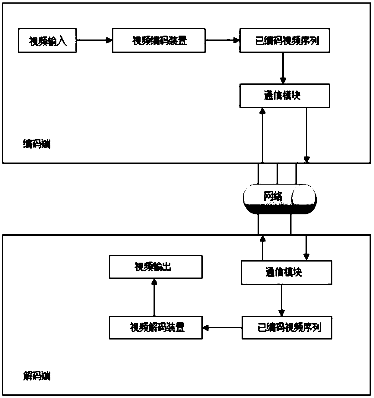
[0072] Figure 4 It is a schematic structural diagram of a video codec system provided in Embodiment 3 of the present invention, Figure 5 It is a schematic flowchart of the image restoration method provided by the third embodiment of the present invention.
[0073] Such as Figure 4 As shown, the video codec system includes an encoding end and a decoding end, and the encoding end includes a video encoding device 401 , an image restoration device 402 , and an image detection device 403 . The decoding end includes an image feedback device 405 and a video decoding device 404 .
[0074] Wherein, the image restoration device 402 at the encoding end is used to adaptively adjust the image target bit to ensure the image quality; the image detection device 403 at the encoding end is used to calculate the inter-frame similarity, reconstruct the image quality, and receive the decoding feedback information fed back by the decoding end, Determine whether to execute the following coding...
PUM
 Abstract
Description
Claims
Application Information
 - R&D
- Intellectual Property
- Life Sciences
- Materials
- Tech Scout
- Unparalleled Data Quality
- Higher Quality Content
- 60% Fewer Hallucinations
Browse by: Latest US Patents, China's latest patents, Technical Efficacy Thesaurus, Application Domain, Technology Topic, Popular Technical Reports.
© 2025 PatSnap. All rights reserved.Legal|Privacy policy|Modern Slavery Act Transparency Statement|Sitemap|About US| Contact US: help@patsnap.com