
cooling fan

A heat dissipation fan and fan blade technology, which is applied in the direction of non-variable pumps, pump components, components of pumping devices for elastic fluids, etc., can solve the problems of slow air flow velocity, poor heat dissipation performance, and reduction. Achieve the effect of reducing the generation of eddy current, reducing the possibility of resonance and low noise

Active Publication Date: 2022-03-08
ACER INC
View PDF8 Cites 0 Cited by
  • Summary
  • Abstract
  • Description
  • Claims
  • Application Information

AI Technical Summary

Problems solved by technology

[0002] Existing axial flow fans are widely used in computer mainframes to dissipate heat. However, the performance of the mainframes of personal computers and servers has developed rapidly recently, and high-performance computer mainframes also generate a lot of waste heat. In order to avoid the accumulation of waste heat and cause the mainframe The operation is not good, how to make a high-flow fan to achieve good heat dissipation is an important goal at present
[0003] In addition, when the existing axial flow fan rotates, the airflow will flow along the surface of the blade. Due to the effect of viscous force, the flow velocity of the airflow on the surface of the blade will gradually slow down, and finally the airflow will separate from the surface of the blade. and form a vortex
The generation of vortex will reduce the air flow through the fan, resulting in poor cooling performance, and the vortex phenomenon will also cause noise problems

Method used


Image

  • cooling fan
  • cooling fan
  • cooling fan

Examples


Embodiment Construction

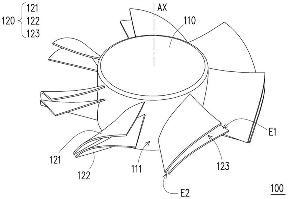
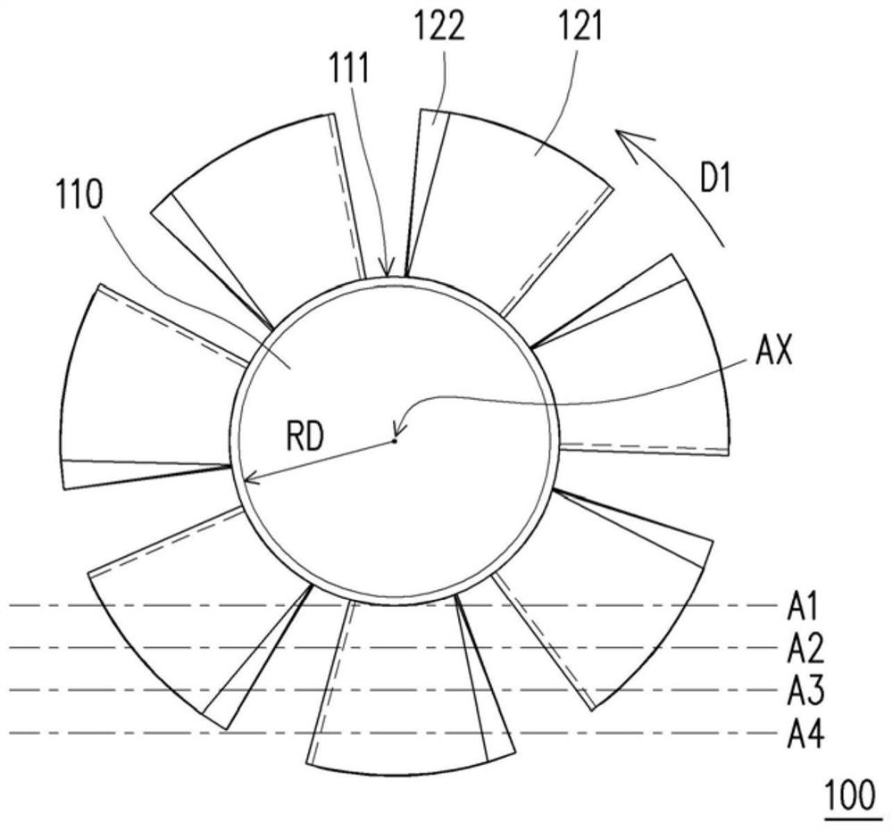
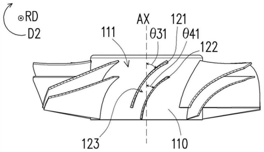
[0038] figure 1 It is a three-dimensional schematic diagram of a heat dissipation fan according to an embodiment of the present invention, and it is viewed from a bottom-up perspective. figure 2 show figure 1 Top view of the cooling fan. Figure 3A to Figure 3D Respectively show partial cross-sectional views of cooling fans at different places, here is figure 2 Corresponding to the different profile lines A1~A4 shown Figure 3A ~ Figure 3D .

[0039] Please refer to figure 1 and figure 2 , in this embodiment, the cooling fan 100 is suitable for disposing in a mainframe computer (such as a laptop, a personal computer or a large server) to dissipate heat for electronic components in the mainframe computer, so as to avoid overheating of the mainframe computer due to the accumulation of waste heat. Here, the cooling fan 100 is, for example, an axial flow fan, which includes a hub 110 and a plurality of blade sets 120 . A plurality of fan blade sets 120 are disposed aroun...


PUM


Abstract

The invention provides a cooling fan, which includes a hub and a plurality of blade sets. A plurality of fan blade groups are arranged around the hub, and each fan blade group includes at least two fan blades, a flow passage is formed between the fan blades, and the width of the flow passage is tapered along the rotation axis of the hub.

Description

technical field [0001] The invention relates to a cooling fan. Background technique [0002] Existing axial flow fans are widely used in computer mainframes to dissipate heat. However, the performance of the mainframes of personal computers and servers has developed rapidly recently, and high-performance computer mainframes also generate a lot of waste heat. In order to avoid the accumulation of waste heat and cause the mainframe How to make a high-flow fan to achieve good heat dissipation is an important goal at present. [0003] In addition, when the existing axial flow fan rotates, the airflow will flow along the surface of the blade. Due to the effect of viscous force, the flow velocity of the airflow on the surface of the blade will gradually slow down, and finally the airflow will separate from the surface of the blade. and form a vortex. The generation of vortex will reduce the air flow through the fan, resulting in poor cooling performance, and the vortex phenomeno...

Claims


Application Information

Patent Timeline
Patent Type & Authority Patents(China)
IPC IPC(8): F04D29/32F04D29/66
CPCF04D29/325F04D29/666
Inventor 林光华谢铮玟廖文能
Owner ACER INC
Learn More