
A cloth sand washing device

A technology of sand washing and cloth, which is applied in the direction of processing textile material carriers, textile material containers, textiles and papermaking, etc., can solve problems such as uneven sand washing, cloth transmission wrinkles, and cloth damage, so as to promote uniform sand washing and save Removing manual operation and avoiding the effect of abrasive damage

Active Publication Date: 2022-08-09
禹旦
View PDF6 Cites 1 Cited by
  • Summary
  • Abstract
  • Description
  • Claims
  • Application Information

AI Technical Summary

Problems solved by technology

However, like other open-width sand washing devices, it has the following disadvantages: 1. When the cloth begins to shuttle between the rollers, manual operation is required, which is cumbersome. When performing this operation, it is necessary to discharge the sand washing liquid, and then send the sand washing liquid back to the sand washing box, which increases the workload of relevant personnel; Wrinkles may occur during the transmission between the sanding boxes, which will lead to uneven sand washing, and may cause damage to the cloth during the sanding process; third, the relevant rollers in the sand washing box are connected to the inner wall of the sand washing box. During the sand washing process, The edges of both sides of the cloth may be rubbed against the side wall of the sand washing box to cause abrasion; 4. In mass production, the winding shaft will be left after the cloth feeding roller is completely fed, and the cloth outlet roller needs to be wound with a winding shaft Cloth requires personnel to transfer the winding shaft, which increases the workload of relevant personnel

Method used


Image

  • A cloth sand washing device
  • A cloth sand washing device
  • A cloth sand washing device

Examples


Embodiment

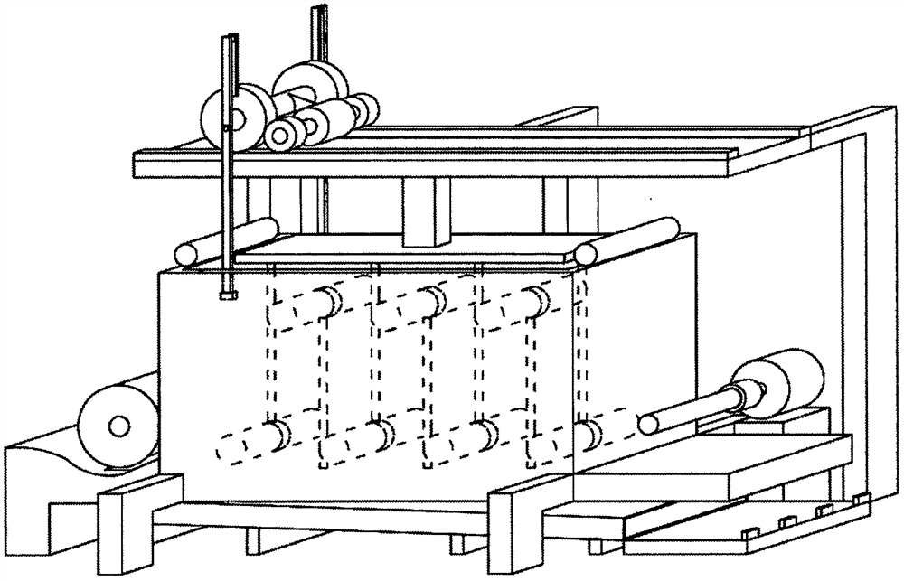
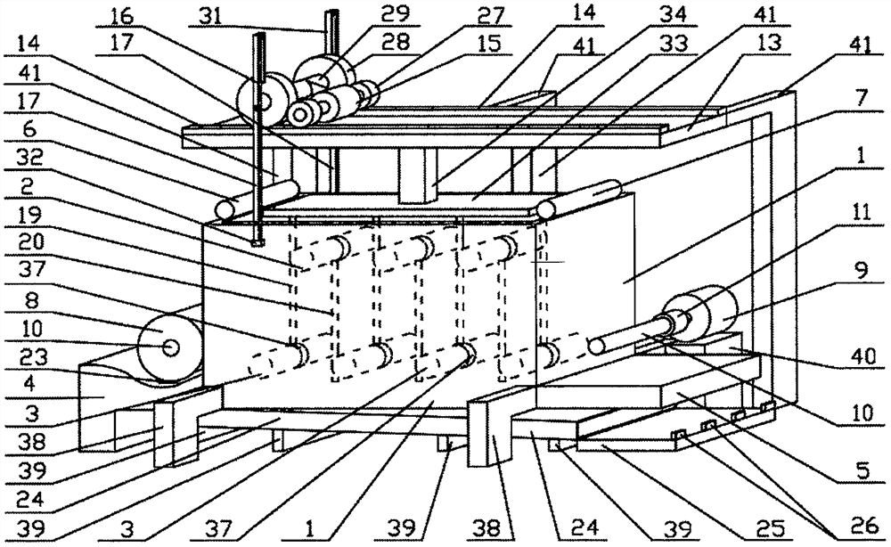
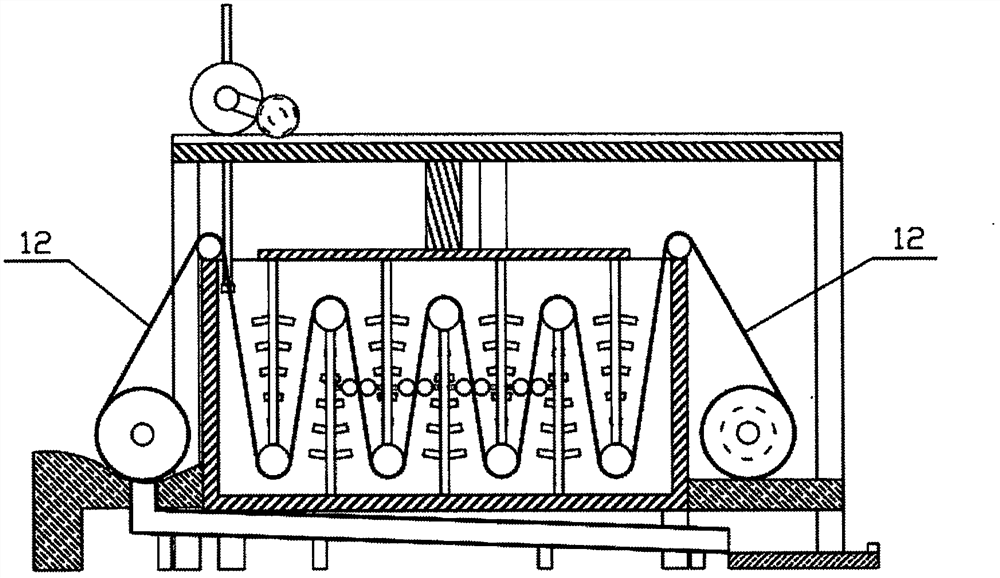
[0036] like Figure 1 to Figure 4 The shown cloth sand washing device includes a sand washing box 1, and the sand washing box 1 is provided with an upper row of rollers 2 and a lower row of rollers 3 arranged equidistantly from the upper row of rollers 2. 1 is filled with sand washing liquid whose liquid level is higher than that of the upper row of rollers 2. The outside of the two ends of the sand washing box 1 is provided with a cloth feeding support table 4 and a cloth rolling support table 5. The top of the sand washing box 1 is two The end sides are respectively provided with a cloth feeding roller 6 and a cloth discharging roller 7. The cloth roll 8 to be sand washed is placed on the cloth feeding support table 4. Rotating motor 9, the output shaft of said rotating motor 9 is provided with a mounting sleeve 11 for installing the winding shaft 10 of the cloth roll 8. During the sand washing process, the cloth 12 shuttles in an "S" shape between the upper rollers 2 and 2....


PUM


Abstract

The invention discloses a cloth sand washing device, belonging to the field of textile production machinery. The cloth feeding support table; the sand washing box is provided with a cloth feeding walking mechanism, which includes two rack tracks arranged on the main support table, and transfer gears are meshed on the two rack tracks. The middle connecting rod and the lifting rod constitute a crank-slider mechanism; the cloth feeding support table is provided with a lower groove, and the bottom of the lower groove is provided with a drop hole that matches the winding shaft of the cloth roll, and a slide rail is connected below the drop hole The cavity, the cavity of the slide rail is gradually lowered from the side of the cloth feeding support table to the side of the cloth rolling support table. The invention can realize the mechanized operation of the shuttle of the cloth head end, can avoid the cloth wrinkle, is beneficial to improve the sand washing effect of the cloth, and also does not need to manually transfer the winding shaft from the side where the cloth feeding support table is located to the side where the cloth rolling support table is located. Greatly reduces the workload of related personnel.

Description

technical field [0001] The invention relates to the field of textile production machinery, in particular to a cloth sand washing device. Background technique [0002] In order to expand the variety of fabrics and improve the performance of fabrics, sand washing technology is widely used. Sand washing is rinsing with an aqueous solution containing alkaline, oxidizing auxiliaries, softeners and other chemical raw materials, so that the clothes have a certain fading effect and become old after washing. If it is matched with graphite, a layer of soft frost-white fluff will be formed on the surface of the fabric after washing, and some softeners will be added to make the fabric soft, soft and thick after washing, thereby improving the comfort of wearing. Sand washing is divided into There are three types of light, medium and heavy washing. After heavy washing, the finished garments have obvious effects such as hand feel and surface fluff, especially heavy silk crepe de chine, sil...

Claims


Application Information

Patent Timeline
Patent Type & Authority Patents(China)
IPC IPC(8): D06B23/18D06B23/04D06C11/00
CPCD06B23/18D06B23/04D06C11/00
Inventor 邹杨邹必尚殷翔芝
Owner 禹旦
Learn More