
Airflow speed reduction balancing part and bass receiver

A technology of balance parts and receivers, which is applied in the field of receivers, can solve the problems of low-frequency distortion increase, etc., and achieve the effects of reducing low-frequency distortion, firm constraints, and less turbulence

Pending Publication Date: 2020-03-06
SUZHOU E AUDIO ELECTRONICS
View PDF1 Cites 1 Cited by
  • Summary
  • Abstract
  • Description
  • Claims
  • Application Information

AI Technical Summary

Problems solved by technology

[0003] Traditional low-frequency armature balanced receivers only do simple acoustic back cavity treatment, such as opening holes on the cavity wall, but opening holes will cause sudden changes in airflow velocity and generate turbulence, which greatly increases low-frequency distortion

Method used


Image

  • Airflow speed reduction balancing part and bass receiver
  • Airflow speed reduction balancing part and bass receiver
  • Airflow speed reduction balancing part and bass receiver

Examples


Embodiment 1

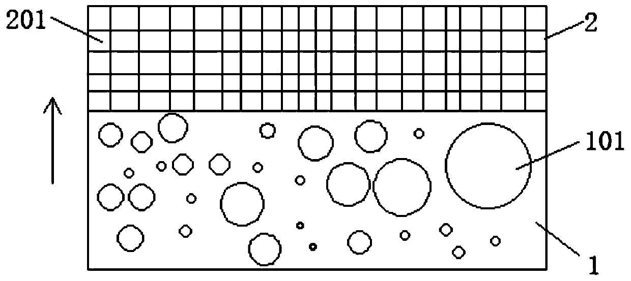
[0028] In order to solve the defect of increased low-frequency distortion existing in the prior art, the present invention provides an airflow deceleration balance piece, such as figure 1 As shown, it includes: airflow deceleration layer 1 and airflow balancing layer 2.

[0029] The airflow deceleration layer 1 is a honeycomb structure, in this embodiment, as figure 1 As shown, the airflow deceleration layer 1 is provided with several circular through holes 101, figure 1 The direction of the middle arrow is the air flow direction, and the axial direction of the circular through hole 101 is perpendicular to the air flow direction, which can absorb and buffer the air flow, but ensure that the air flow can pass through the airflow deceleration layer 1 and reach the airflow balance layer 2 . The diameters of the circular through holes 101 in this embodiment are different, but it is not limited thereto. In another embodiment, the diameters of the circular through holes 101 may als...

Embodiment 2

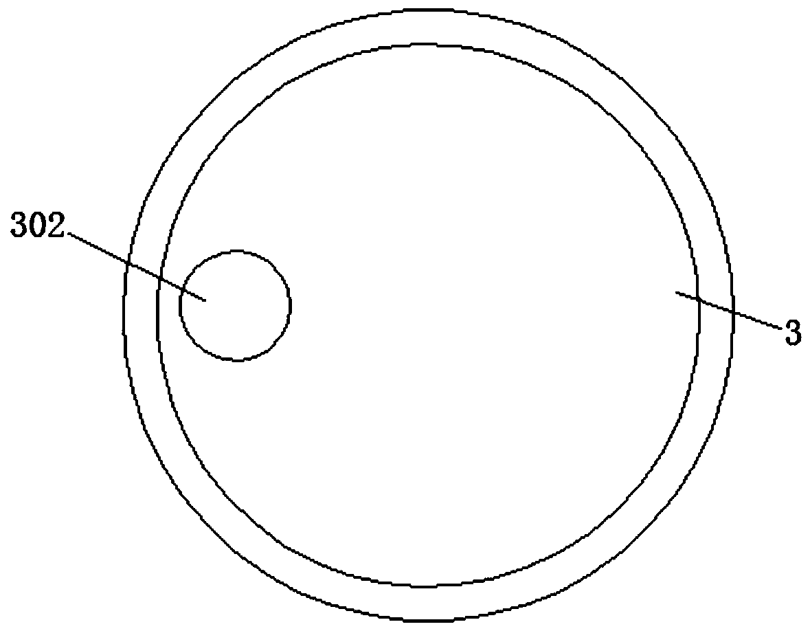
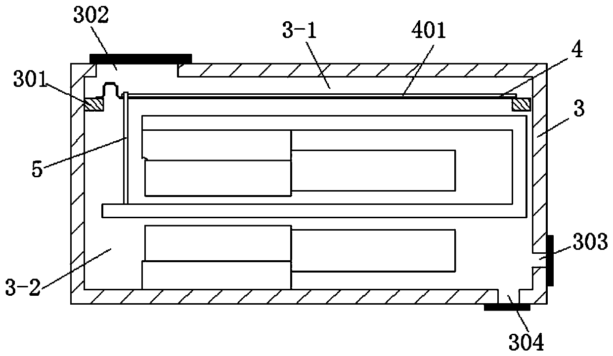
[0035] This embodiment provides a bass receiver, such as figure 2 and 3 As shown, it includes a housing 3 , a diaphragm 4 , a magnetic drive mechanism, and the airflow deceleration balance in Embodiment 1.

[0036] In an embodiment, the housing 3 is cylindrical, such as image 3 As shown, the housing 3 is provided with a frame 301 for supporting the diaphragm 4, specifically, the frame 301 is a ring structure, that is, it is arranged around the inner wall of the housing 3, and the diaphragm 4 is arranged on the frame 301 to divide the housing 3 into a front acoustic air cavity 3-1 and a rear acoustic air cavity 3-2, in image 3 Among them, that is, the upper space of the diaphragm 4 is the front acoustic air cavity 3-1, and the lower space of the diaphragm 4 is the rear acoustic air cavity 3-2.

[0037] At present, the traditional receiver adopts a diaphragm with no hinge structure, and the middle position of the diaphragm adopts a stainless steel connecting rod with a dia...


PUM


Abstract

The invention provides an airflow speed reduction balancing part and a bass receiver, and belongs to the field of receivers, and the airflow speed reduction balancing part comprises an airflow speed reduction layer which is of a honeycomb-shaped structure and is used for absorbing and buffering airflow; the airflow balancing layer and the airflow speed reducing layer are arranged in a stacked mode, and the airflow balancing layer is of a net structure and used for balancing airflow passing through the airflow speed reducing layer. The bass receiver comprises a shell, a vibrating diaphragm, a magnetic driving mechanism and the three airflow speed reduction balance parts, and the three airflow speed reduction balance parts are arranged at the sound outlet hole, the low-speed airflow balancehole and the high-speed airflow balance hole of the shell respectively. The airflow speed reduction balance part can be used for a sound outlet hole and an airflow balance hole of a telephone receiver, so that the output vibration speed is reduced, turbulence is reduced, and low-frequency distortion is reduced.

Description

technical field [0001] The invention belongs to the field of receivers, and in particular relates to an airflow speed reduction balance piece. In addition, the invention also relates to a receiver including the airflow speed reduction balance piece. Background technique [0002] A receiver is an electro-acoustic device that converts audio electrical signals into sound signals, and is widely used in mobile phones, landline phones, hearing aids, earphones and other equipment. [0003] Traditional low-frequency armature balance receivers only do simple acoustic back cavity treatment, such as opening holes on the cavity wall, but opening holes will cause sudden changes in airflow velocity and generate turbulence, which greatly increases low-frequency distortion. Contents of the invention [0004] Based on the above-mentioned background problem, the present invention aims to provide an airflow speed reduction balance piece, which can be used in the sound hole and the airflow ba...

Claims


Application Information

Patent Timeline
Patent Type & Authority Applications(China)
IPC IPC(8): H04R1/02H04R1/08H04R1/28
CPCH04R1/02H04R1/08H04R1/2807H04R1/2869H04R2201/02
Inventor 薛洪明施明明张春刚
Owner SUZHOU E AUDIO ELECTRONICS
Learn More