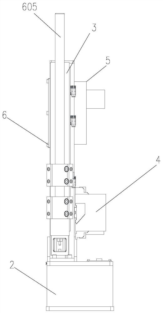
A glass level gauge

A technology of liquid glass and columns, which is applied in the direction of liquid level indicators for physical variable measurement, can solve problems such as easy material hanging, probe overshoot, and large inertia of the transmission mechanism, so as to reduce production costs, ensure measurement accuracy, and reduce costs. The effect of inertial transmission

Active Publication Date: 2020-10-30
XIAN WEIMIKE AUTOMATIC CONTROL INSTR TECH
View PDF7 Cites 0 Cited by
  • Summary
  • Abstract
  • Description
  • Claims
  • Application Information

AI Technical Summary

Problems solved by technology

Due to the special environment and medium, traditional radar and laser cannot accurately measure the liquid level of molten glass
[0004] At present, the representative glass liquid level gauge produced by a certain company in the United States on the market drives the probe for sensing the liquid level to move up and down through the rack and pinion transmission, and the movement distance is measured by the displacement sensor, because there is a gap between the rack and pinion transmission. , and the gap is not uniform, resulting in large errors and instability. It is difficult to calibrate the zero point when measuring with a displacement sensor. There is a phenomenon of drift in the output. The inertia of the transmission mechanism is large. After the probe is triggered, the probe will overshoot due to mechanical gaps and other reasons. , causing the glass probe to touch the glass liquid too deeply, and it is easy to hang the material

Method used


Image

  • A glass level gauge
  • A glass level gauge
  • A glass level gauge

Examples


Embodiment Construction

[0034] Example embodiments will now be described more fully with reference to the accompanying drawings. Example embodiments may, however, be embodied in many forms and should not be construed as limited to the examples set forth herein; rather, these embodiments are provided so that this disclosure will be thorough and complete and fully convey the concept of example embodiments to those skilled in the art. The described features, structures, or characteristics may be combined in any suitable manner in one or more embodiments.

[0035] In addition, the drawings are merely schematic illustrations of embodiments of the present invention and are not necessarily drawn to scale. The same reference numerals in the drawings denote the same or similar parts, and thus repeated descriptions thereof will be omitted. Some of the structural diagrams shown in the drawings are functional entities and do not necessarily correspond to physically or logically separate entities.

[0036] Suc...


PUM


Abstract

The invention provides a glass liquid level meter. The glass liquid level meter comprises a base used for being fixed to a user field mounting base, a stand column used for being matched with the baseto form a supporting frame, a controller used for recording and transmitting signals, a single-axis robot used for controlling a probe to move up and down, and a servo driver used for controlling thesingle-axis robot. The stand column is vertically arranged above the base, the controller is arranged on the stand column and located at the end close to the base, the single-axis robot is arranged on the stand column and located on the side adjacent to the controller, and the servo driver is arranged on the stand column and located on the side opposite to the single-axis robot. The integrated design is adopted, the structure is compact, maintenance is convenient, the production cost is effectively reduced, and the reliability of the device is improved; and moreover, linear guide rail guidingand ball screw displacement transmission are adopted, interference fit is adopted, no transmission gap exists, and therefore, high-precision and low-inertia transmission is achieved, and the measurement precision of the whole device is guaranteed.

Description

technical field [0001] The invention relates to the technical field of special equipment for the glass industry, in particular to a glass liquid level height measuring device. Background technique [0002] As a light-transmitting material, glass is widely used in construction, automobile and other industries as well as in daily life. During the process of making glass, glass manufacturers need to monitor various aspects of the glass, such as the height of the liquid level of the glass. [0003] Under normal circumstances, the temperature of the molten glass is as high as 1500-1600 degrees. After precipitation, it enters the forming process through the platinum channel for stretching. In this process, it is necessary to control an important process parameter—the height of the liquid level of the molten glass to ensure the forming and control. Feeding. Due to the special environment and medium, traditional radar and laser cannot accurately measure the liquid level of molten ...

Claims


Application Information

Patent Timeline
Patent Type & Authority Patents(China)
IPC IPC(8): G01F23/22
CPCG01F23/22
Inventor 王均利程刚
Owner XIAN WEIMIKE AUTOMATIC CONTROL INSTR TECH
Why Eureka
Try Eureka