
Rotary spot welding machine of clutch assembly

A technology of spot welding machine and clutch, which is applied in the direction of welding equipment, auxiliary welding equipment, welding/cutting auxiliary equipment, etc., which can solve the problems of many times of mechanical arm movement, lower system stability, and complex spatial movement control coordinates, etc., to achieve Precise adjustment, the effect of improving the overall efficiency

Inactive Publication Date: 2020-03-06
湖北正航汽车部件有限公司
View PDF0 Cites 1 Cited by
  • Summary
  • Abstract
  • Description
  • Claims
  • Application Information

AI Technical Summary

Problems solved by technology

[0002] The clutch is a transmission part set between the engine and the reduction box. During the processing of the clutch, spot welding is required. For example, welding is used to fix the clutch hub and the sleeve shaft. However, the traditional electric welding gun passes The mechanical arm moves the electric welding torch to each welding point for welding one by one. The number of movements of the mechanical arm is large, and the control coordinates of space movement are complicated, which reduces the stability of the system and reduces the efficiency of spot welding. During the processing, many The welding points are distributed in a circle, which can be used for circular welding, which can improve the overall efficiency of spot welding

Method used


Image

  • Rotary spot welding machine of clutch assembly
  • Rotary spot welding machine of clutch assembly
  • Rotary spot welding machine of clutch assembly

Examples


Embodiment 1

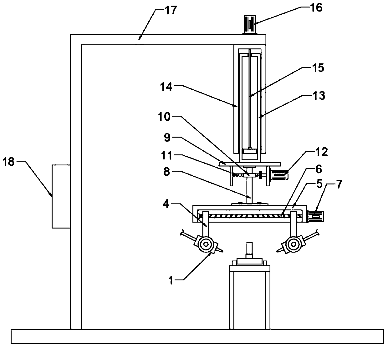
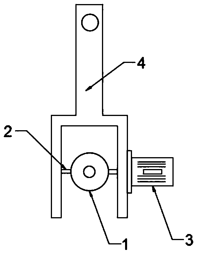
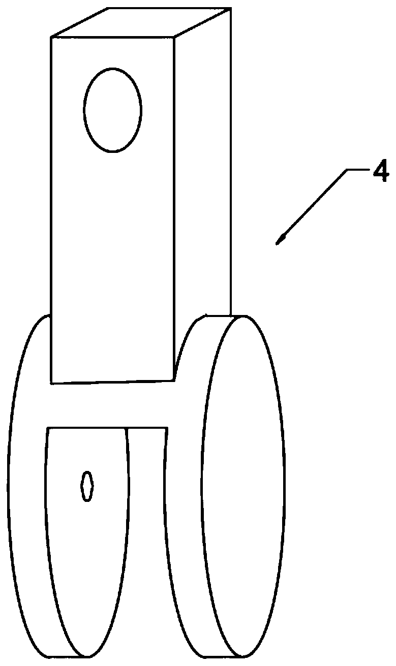
[0019] see Figure 1-3 , in an embodiment of the present invention, a rotary spot welding machine for a clutch assembly includes a welding machine body; Frame 4, the rotating shaft 2 is connected with the output shaft of the first drive motor 3 through a shaft coupling, the first drive motor 3 is respectively connected with a controller 18 and an external power supply through a wire, and the controller 18 is a PLC controller, which is started by the controller 18 The first driving motor 3, the first driving motor 3 drives the spot welding torch 1 to rotate, adjusts the welding angle of the spot welding torch, and then adapts to different welding angles, has good adaptability, especially for the welding points on the clutch assembly mostly in the shape of Circumferential distribution, with good adaptability.

[0020] The upper end of the mobile frame 4 is nested with a rotating slot plate 5, the rotating slot plate 5 is provided with a rectangular chute with an opening downwar...

Embodiment 2

[0023] The difference between this embodiment and Embodiment 1 is that: the upper end of the lifting plate 9 is fixedly connected with a lifting mechanism, and the lifting mechanism includes a lifting frame 13 fixedly connected with the lifting plate 9, and the lifting frame 13 runs through a fixed frame 14, and the fixed frame 14 is Rectangular frame, fixed frame is fixedly connected with installation frame 17; Described elevating frame 13 penetrates and is threadedly connected with screw mandrel 15, and screw mandrel 15 is connected with the second screw mandrel motor 16 by shaft coupling, and the second screw mandrel motor 16 and installation The frame 17 is fixedly connected, and the second screw motor 16 drives the screw rod 15 to rotate, and then drives the lifting frame 13 to move up and down, and then drives the lifting plate 9 and the parts on it to move up and down, and then adjusts the height of the spot welding gun 1, which has height adjustment Ability to adapt to ...


PUM


Abstract

The invention discloses a rotary spot welding machine of a clutch assembly. The rotary spot welding machine comprises a welding machine body. The welding machine body comprises a group of angle adjustable spot welding guns arranged oppositely, the spot welding guns are rotatably connected to a moving rack, a rotating trough plate is embedded onto the upper end of the moving rack, a bidirectional lead screw of the moving rack is arranged in the rotating trough plate, and the bidirectional lead screw is connected to a first lead screw motor through a coupling; and a rotating shaft is fixedly connected to the rotating trough plate. By arranging the rotating shaft and a first driving motor, the angles of the spot welding guns are adjusted conveniently. By arranging the rotating trough plate, the moving rack and the bidirectional lead screw, and the separation distances between the spot welding guns are adjusted conveniently, so that double points are welded simultaneously. By arranging therotating shaft and a worm wheel and a worm, the active angles of the spot welding guns are adjusted precisely, and welding points distributed circumferentially are welded rotatably, so that the integral welding efficiency is improved.

Description

technical field [0001] The invention relates to the field of auto parts processing equipment, in particular to a spin spot welding machine for a clutch assembly. Background technique [0002] The clutch is a transmission part set between the engine and the reduction box. During the processing of the clutch, spot welding is required. For example, welding is used to fix the clutch hub and the sleeve shaft. However, the traditional electric welding gun passes The mechanical arm moves the electric welding torch to each welding point for welding one by one. The number of movements of the mechanical arm is large, and the control coordinates of space movement are complicated, which reduces the stability of the system and reduces the efficiency of spot welding. During the processing, many The welding points are all distributed in a circle, and circular welding can be performed, which can improve the overall efficiency of spot welding. Contents of the invention [0003] The object...

Claims


Application Information

Patent Timeline
IPC IPC(8): B23K37/00B23K37/02
CPCB23K37/00B23K37/0247
Inventor 陈友冲许新武何兆林赵伟肖虎
Owner 湖北正航汽车部件有限公司
Learn More