
Wire drawing machine for precision screw production

A wire drawing machine and screw technology, which is applied in metal wire drawing, metal processing equipment, manufacturing tools, etc., can solve the problems of low output efficiency of wire rods, low processing efficiency of wire drawing machines, etc., and achieves easy cutting of wire columns, high processing efficiency, The effect of improving transmission efficiency

Inactive Publication Date: 2020-03-06
江苏博凡科精密五金科技有限公司
View PDF5 Cites 0 Cited by
  • Summary
  • Abstract
  • Description
  • Claims
  • Application Information

AI Technical Summary

Problems solved by technology

[0004] The object of the present invention is to provide a wire drawing machine for precision screw production in order to solve the above problems, which solves the problem that the existing wire drawing machine for screw production usually uses a traction wheel transmission mode to carry out wire transmission, and intercepts longer lengths of wire. When the column is used, the output efficiency of the wire is low, which makes the processing efficiency of the wire drawing machine low.

Method used


Image

  • Wire drawing machine for precision screw production
  • Wire drawing machine for precision screw production
  • Wire drawing machine for precision screw production

Examples


Embodiment

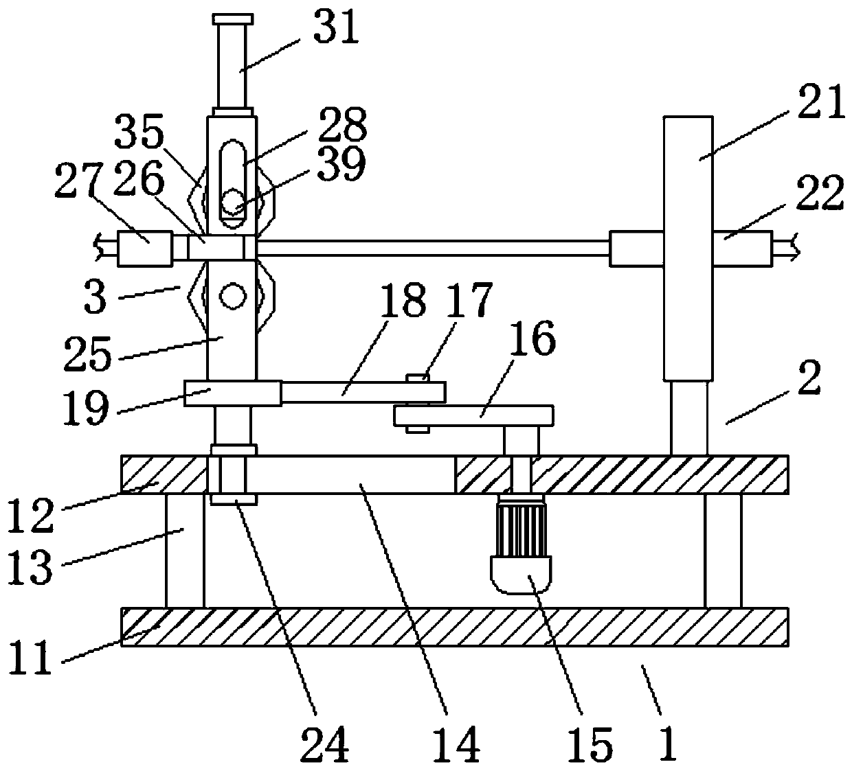
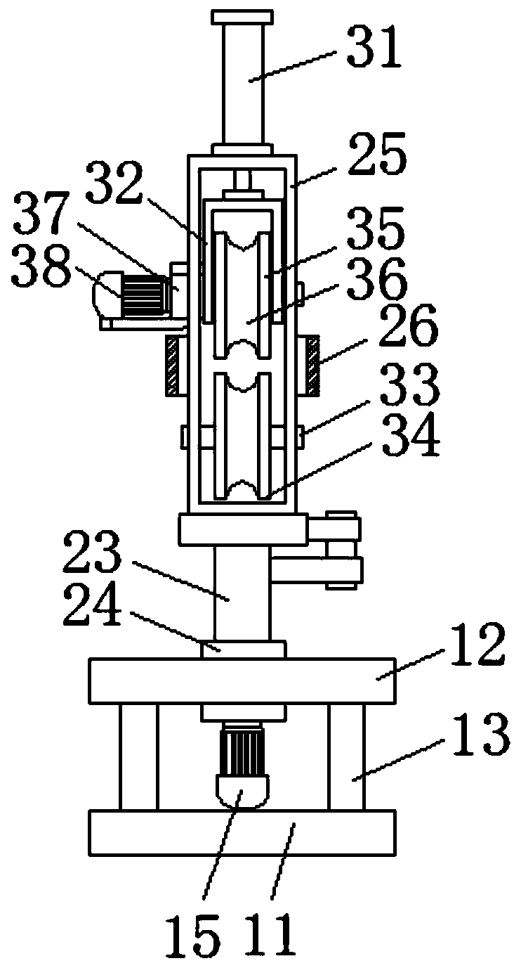
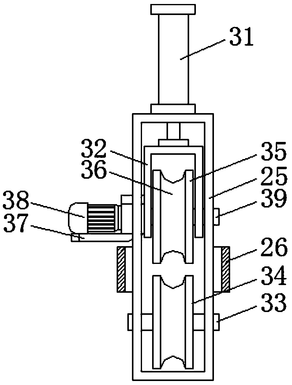
[0023] Example: such as Figure 1-5 As shown, a wire drawing machine for precision screw production of the present invention includes a reciprocating mechanism 1, a wire drawing mechanism 2 and a wire feeding mechanism 3, a wire drawing mechanism 2 is installed in the reciprocating mechanism 1, and a wire feeding mechanism is installed in the wire drawing mechanism 2 Institution 3.

[0024] Wherein, the reciprocating mechanism 1 comprises a base plate 11, a top plate 12, a strut 13, a transverse chute 14, a No. 1 motor 15, a fixed rod 16, a connecting pin 17, a movable rod 18 and a rotary sleeve 19, and the top plate 12 is provided above the base plate 11. , four struts 13 are fixedly connected between the bottom plate 11 and the top plate 12, and the top plate 12 is provided with a transverse chute 14, and the underside screw of the top plate 12 is fixed with a No. A fixed rod 16 is fixedly connected, and the fixed rod 16 is rotatably connected with a movable rod 18 through ...


PUM


Abstract

The invention discloses a wire drawing machine for precision screw production. The wire drawing machine comprises a reciprocating mechanism, a wire drawing mechanism and a wire conveying mechanism, wherein the reciprocating mechanism is internally provided with the wire drawing mechanism, the wire drawing mechanism is internally provided with the wire conveying mechanism, the reciprocating mechanism comprises a bottom plate, a top plate, supporting rods, a transverse sliding groove, a first motor, a fixing rod, a connection pin, a movable rod and a rotating sleeve, the top plate is arranged above the bottom plate, the four supporting rods are fixedly connected between the bottom plate and the top plate, the transverse sliding groove is formed in the top plate, the first motor is fixed to the lower side of the top plate through a screw, and the output end of the first motor penetrates through the top plate to be fixedly connected with the fixing rod. The wire drawing machine for precision screw production has the characteristics of being reasonable in structural design and high in machining efficiency, the conveying efficiency of a wire is greatly improved by adopting the mode of combining the reciprocating mechanism and the wire conveying mechanism when the wire drawing machine is used, meanwhile, an air cylinder is arranged so that a driving wheel can compress the wire, and the phenomena of slipping and the like of a traction wheel can be effectively avoided.

Description

technical field [0001] The invention relates to a thread drawing machine, in particular to a thread drawing machine for precision screw production, which belongs to the technical field of screw processing. Background technique [0002] The wire used for screw production needs to be pickled before drawing, which can remove the oxide film on the surface of the wire and form a phosphate film, which can minimize the damage to the mold caused by rough wire and sundries. After pickling, the wire must be cooled by a wire drawing machine Pull to the desired radius and then cut to make the stud into a nail blank. [0003] Existing wire drawing machines for screw production mostly use traction wheel transmission for wire transmission. In order to ensure the accuracy of the cutting length, the speed of the traction wheel for wire shearing is relatively slow. When cutting a long length of wire post, the wire The output efficiency is low, which makes the processing efficiency of the wir...

Claims


Application Information

Patent Timeline
Patent Type & Authority Applications(China)
IPC IPC(8): B21C1/02B21C1/14B21C19/00
CPCB21C1/02B21C1/14B21C19/00
Inventor 汤继勇
Owner 江苏博凡科精密五金科技有限公司
Learn More