
Fan frame capable of reducing noise

A fan and fan frame technology, applied to parts of pumping devices for elastic fluids, non-variable pumps, machines/engines, etc., can solve problems such as mutual impact, increased noise at the air inlet 13, and increased noise

Active Publication Date: 2020-03-03
SUNONWEALTH ELECTRIC MACHINE IND
View PDF11 Cites 2 Cited by
  • Summary
  • Abstract
  • Description
  • Claims
  • Application Information

AI Technical Summary

Problems solved by technology

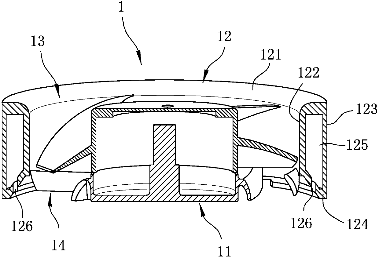
[0004] However, in order to form the cavity 125 inside the outer frame body 12, the design of increasing the area of ​​the top wall portion 121 is adopted, which increases the windward area of ​​the outer frame body 12 toward the air inlet 13, On the contrary, the noise at the air inlet 13 is increased; moreover, the thick outer frame shape of the top wall portion 121 of the outer frame body 12 does not conform to the current trend of pursuing thin and light fan frames without taking up space; After 126 enter the same chamber 125, they are easy to collide with each other due to the opposite directions, and finally resonate in the chamber 125, which instead causes the noise to increase. Therefore, the fan frame 1 still needs to be improved in terms of noise reduction

Method used


Image

  • Fan frame capable of reducing noise
  • Fan frame capable of reducing noise
  • Fan frame capable of reducing noise

Examples


Embodiment Construction

[0027] The present invention will be described in detail below in conjunction with the accompanying drawings and embodiments.

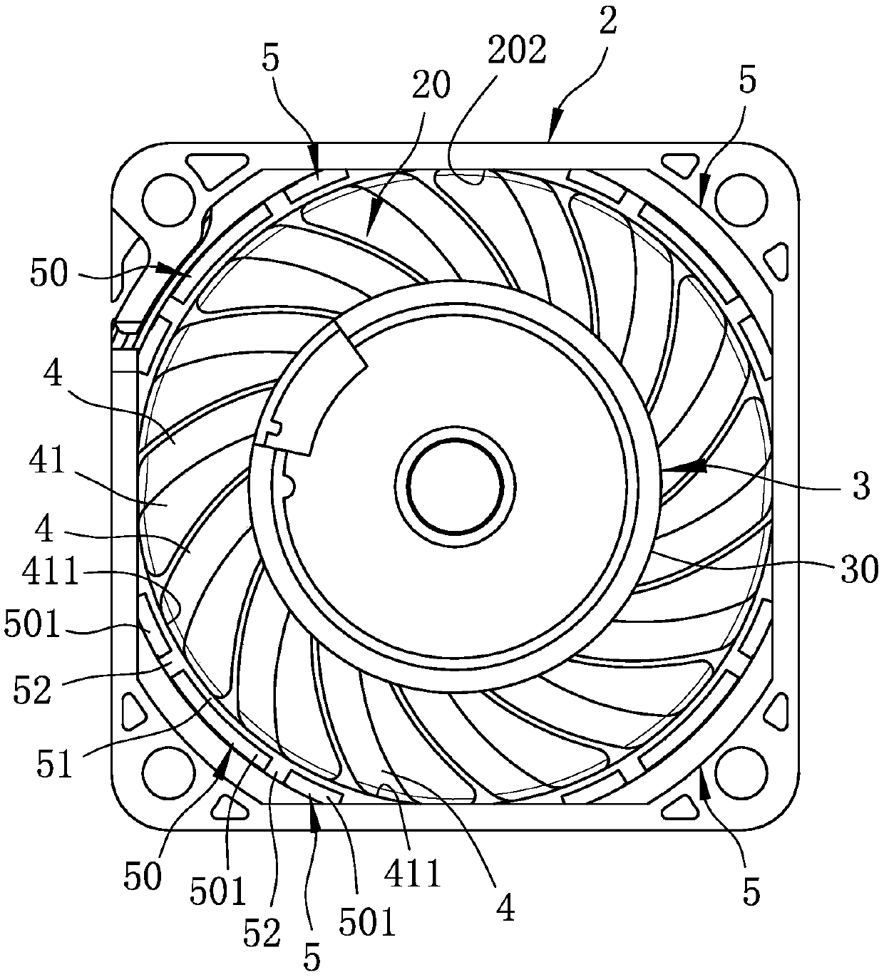
[0028] refer to image 3 and Figure 4 , the first embodiment of the noise-reducing fan frame of the present invention includes an outer frame body 2 surrounding an inner space 20, and a shaft tube located in the inner space 20 and surrounded by the outer frame body 2 Seat 3 , a plurality of stator blades 4 extending from the outer wall surface 30 of the shaft tube seat 3 toward the outer frame body 2 , and four partitions 5 connecting several of the stator blades 4 . In this first embodiment, the outer frame body 2 is composed of the upper and lower parts by buckling, but it can also be an integrally formed design, which should not be limited thereto. The inner space 20 has an An air outlet 201, and an air outlet 202 located below the air inlet 201, the inner space 20 can be used for air flow along a flow direction A (in this first embodiment, the ...


PUM


Abstract

A fan frame capable of reducing noise comprises an outer frame body surrounding an inner space, a shaft tube base located in the inner space, a plurality of static blades extending from the outer wallface of the shaft tube base to the outer frame body, and a plurality of partition plates. Each partition plate is connected with at least one of the static blades and the inner wall face of the outerframe body. The internal space is provided with an air inlet and an air outlet. Each static blade is arranged on the shaft tube seat along the flowing direction far away from the bottom of the shafttube seat. Each partition plate is matched with the outer frame body to define a partition space communicating with the inner space; due to the design of the separation space, the effect of noise reduction can be achieved, a cavity does not need to be formed by increasing the size of the outer frame body, and therefore, the outer frame body can be designed to be light and thin, the windward area can be reduced, and noise at the air inlet and the air outlet can be restrained at the same time.

Description

technical field [0001] The invention relates to a frame, in particular to a fan frame. Background technique [0002] With the continuous advancement of technology, the size of integrated circuits and electronic components is becoming more and more miniaturized, so they can be configured with higher density, resulting in powerful computing power and functionality, but also require good heat dissipation to maintain normal work A common heat dissipation fan is a heat dissipation device that drives airflow or fluid through rotating fan blades to achieve a good air cooling effect. General heat dissipation fans are often accompanied by unpleasant noises when they are running. Noise generated at the air inlet and outlet due to turbulence or flow field disturbance. The main cause of the former is the overall vibration caused by the fan blades, which causes the fan frame to collide with the environment where it is installed and make noise. Usually, the noise can be reduced by insta...

Claims


Application Information

Patent Timeline
IPC IPC(8): F04D29/52F04D29/54F04D29/66
CPCF04D29/522F04D29/542F04D29/667
Inventor 洪银树倪薪富
Owner SUNONWEALTH ELECTRIC MACHINE IND
Learn More