Monitoring Method of Compression and Tensile Deformation of Stressed Rods Based on Optical Fiber Sensing Technology

An optical fiber sensing and tensile deformation technology, which is used in measurement devices, using stable tension/pressure to test the strength of materials, instruments, etc., can solve the problem of inability to obtain data quickly, low monitoring coverage density, and inability to ensure the personal safety of measurement personnel. and other problems, to achieve the effect of non-interference measurement, sensitivity and accuracy improvement, and high sensitivity

Active Publication Date: 2022-04-05
SHANGHAI TUNNEL ENGINEERING RAILWAY TRANSPORTATION DESIGN INSTITUTE
View PDF10 Cites 0 Cited by
  • Summary
  • Abstract
  • Description
  • Claims
  • Application Information

AI Technical Summary

Problems solved by technology

[0002]In the current foundation pit construction, the collapse caused by the instability of the foundation pit slope may cause major safety risks or accidents in the foundation pit and surrounding building facilities
At present, in the monitoring of the foundation pit construction process, manual on-site measurement is mostly used, and the construction site is monitored through instruments such as full rotation instruments, levels, and reading instruments. This method often takes a lot of time for technicians, resulting in the inability to quickly obtain data. , using manual monitoring, which often has a small monitoring coverage density, cannot meet the requirements of early warning, and cannot guarantee the personal safety of surveyors

Method used


Image

  • Monitoring Method of Compression and Tensile Deformation of Stressed Rods Based on Optical Fiber Sensing Technology
  • Monitoring Method of Compression and Tensile Deformation of Stressed Rods Based on Optical Fiber Sensing Technology
  • Monitoring Method of Compression and Tensile Deformation of Stressed Rods Based on Optical Fiber Sensing Technology

Examples


Embodiment

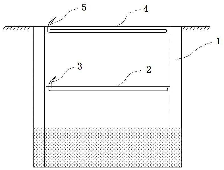
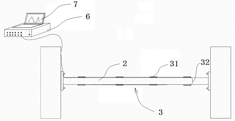
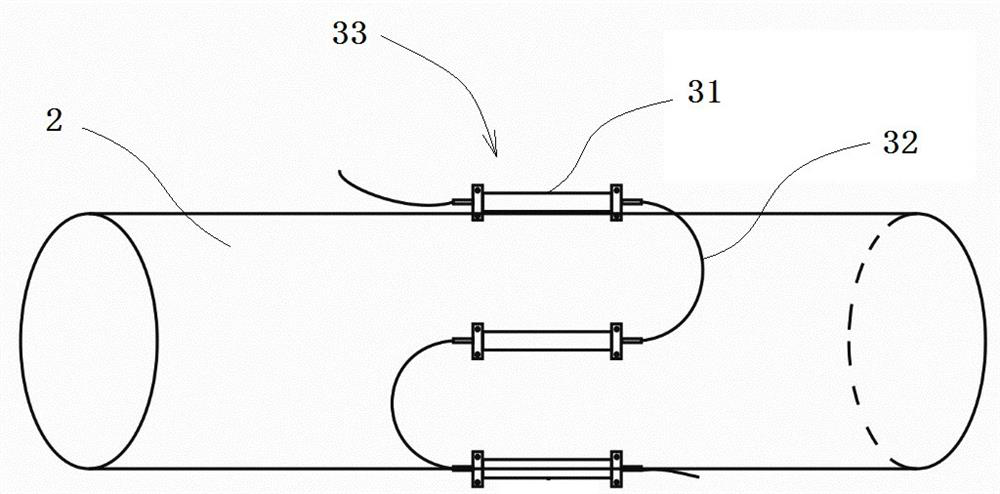
[0027] Example: such as Figure 1-4 As shown, this embodiment specifically relates to a method for monitoring the compression and tensile deformation of a stressed rod based on optical fiber sensing technology, which specifically includes the following steps:

[0028] (1) According to the engineering needs, determine the area of ​​the supporting rods to be tested in the foundation pit enclosure structure 1, and determine the distance between each fixing ring according to the needs;

[0029] (2) For different types of support rods, choose different installation methods:

[0030] If the support bar is a concrete support 4, then the quasi-distributed steel stress sensing optical cable 5 is arranged along the axial direction of the concrete support 4, and the quasi-distributed steel stress sensing optical cable 5 is specifically bundled and arranged in two symmetrically arranged in the concrete support 4. on the main bar, and form a U-shaped return circuit; the quasi-distributed ...


PUM


Abstract

The invention discloses a method for monitoring the compression and tensile deformation of stressed rods based on optical fiber sensing technology, which includes the following steps: selecting different sensing Optical cables are installed, that is, quasi-distributed steel stress sensing optical cables or quasi-distributed fiber Bragg grating strain sensing optical cables. The above-mentioned sensing optical cables are connected to the FBG demodulator; the FBG demodulator sends out broadband optical signals and transmits them to the sensing optical cables. And reflect a set of narrow-band light with different wavelengths; when the sensing optical cable changes with the support rod, the resonant wavelength of the sensing optical cable will drift, and the wavelength of the reflected narrow-band light will be identified by the FBG demodulator, and the narrow-band light will be monitored The wavelength change of the beam is used to determine whether the support rod is stretched or compressed. The invention has the advantages that: compared with the traditional point-type monitoring method, quasi-distributed monitoring is realized by using the optical fiber sensing technology, and the convenience, sensitivity and precision of the measurement are greatly improved.

Description

technical field [0001] The invention belongs to the technical field of automatic monitoring, and in particular relates to a method for monitoring compression and tensile deformation of stressed rods based on optical fiber sensing technology. Background technique [0002] In the current foundation pit construction, the collapse caused by the instability of the foundation pit slope may cause major safety risks or accidents in the foundation pit and surrounding building facilities. At present, in the monitoring of the foundation pit construction process, manual on-site measurement is mostly used, and the construction site is monitored through instruments such as full rotation instruments, levels, and reading instruments. This method often takes a lot of time for technicians, resulting in the inability to quickly obtain data. , using manual monitoring, which often has a small monitoring coverage density, cannot meet the requirements of early warning, and cannot guarantee the per...

Claims


Application Information

Patent Timeline
Patent Type & Authority Patents(China)
IPC IPC(8): G01N3/06G01N3/08
CPCG01N3/068G01N3/08G01N2203/0017G01N2203/0019G01N2203/0075G01N2203/0641
Inventor 王成荣丁利红陈鸿叶蓉刘朝明陈培泰徐克洋唐耀华贾立翔阳侣胡有宝金奚钱存超潘骏
Owner SHANGHAI TUNNEL ENGINEERING RAILWAY TRANSPORTATION DESIGN INSTITUTE
Why Eureka
Try Eureka