
Roadbed compaction degree detection device

A detection device and compaction technology, which is applied in the field of foundation soil survey, basic structure engineering, construction, etc., can solve the problems of small size, floor and subgrade moving up, insufficient to meet the needs, and achieve the overall easy operation, disassembly and assembly Easy to operate, fixed and easy to operate

Inactive Publication Date: 2020-02-28
孙琴
View PDF7 Cites 0 Cited by
  • Summary
  • Abstract
  • Description
  • Claims
  • Application Information

AI Technical Summary

Problems solved by technology

[0004] 1. The base plate is laid flat on the surface of the subgrade. When working, the long column and the short column pass through the base plate and are inserted into the subgrade, but the base plate is only placed on the subgrade, and the two do not have a fixed effect. When the hydraulic cylinder works, the long column and the short column move down. It is easy to make the bottom plate move up relative to the roadbed, so that the long and short columns cannot be inserted into the roadbed;
[0005] 2. In order to facilitate the insertion of the long column and the short column, the thickness of the long column and the short column itself is relatively small (thicker is not easy to insert under the subgrade), so that the retractable tunneling head installed in the long column and short column The volume of the soil is relatively small, which ultimately makes the volume of the blind hole on the tunneling head for soil extraction limited, so that the single soil volume is not enough to meet the soil volume required for multiple comparison experiments

Method used

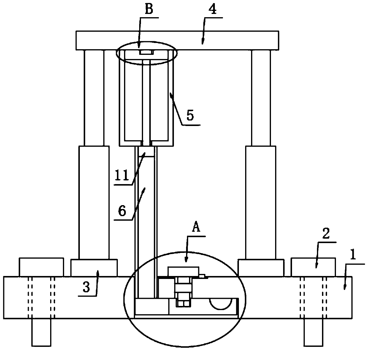

Image

  • Roadbed compaction degree detection device
  • Roadbed compaction degree detection device
  • Roadbed compaction degree detection device

Examples


Embodiment Construction

[0026] The following will clearly and completely describe the technical solutions in the embodiments of the present invention with reference to the accompanying drawings in the embodiments of the present invention. Obviously, the described embodiments are only some, not all, embodiments of the present invention. Based on the embodiments of the present invention, all other embodiments obtained by persons of ordinary skill in the art without making creative efforts belong to the protection scope of the present invention.

[0027] In describing the present invention, it should be understood that the terms "upper", "lower", "front", "rear", "left", "right", "top", "bottom", "inner", " The orientation or positional relationship indicated by "outside", etc. is based on the orientation or positional relationship shown in the drawings, and is only for the convenience of describing the present invention and simplifying the description, rather than indicating or implying that the referre...


PUM


Abstract

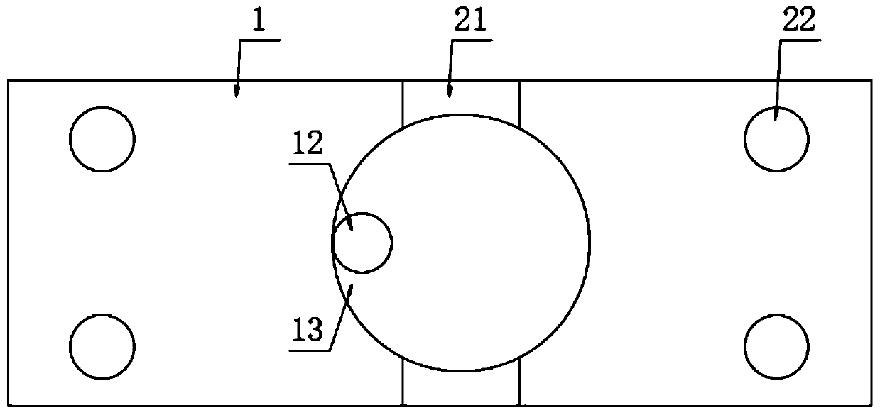
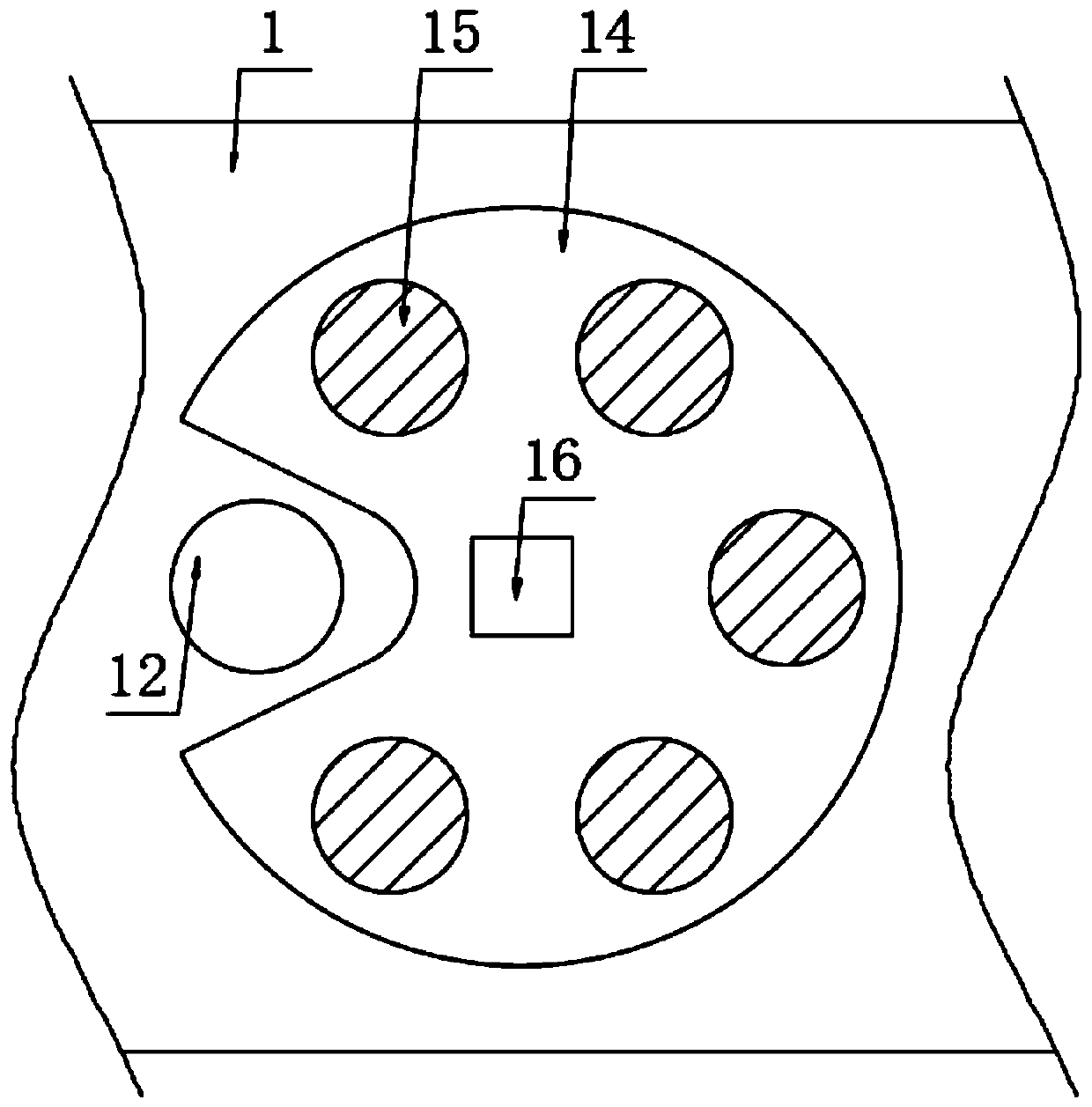
The invention discloses a roadbed compaction degree detection device. The roadbed compaction degree detection device comprises a placement seat placed on a roadbed, wherein a plurality of fixed screwrods are mounted on the placement seat through threads; the lower ends of the fixed screw rods are positioned in the roadbed; the placement seat is commonly provided with a lifting plate capable of lifting through two groups of hoisting structures; a soil taking barrel is fixedly mounted on the lower surface of the lifting plate through a mounting frame; the soil taking barrel is of a hollow structure with two communicated ends; the lifting plate is provided with a lower pressing plate through a mounting structure; a connecting rod is fixedly mounted on the lower surface of the lower pressingplate; the lower end of the connecting rod penetrates through the mounting frame and is fixedly provided with a lower pressing block. The roadbed compaction degree detection device disclosed by the invention has the advantages that the fixation operation of the placement seat on the roadbed is simple and convenient and soil taking operation is convenient to rapidly mount; the amount of roadbed soil which is taken out at a time is relatively more and the soil utilization amount needed by a plurality of groups of comparison experiments can be met; meanwhile, after the soil taking operation is finished, the roadbed soil which is taken out from the soil taking barrel can be rapidly collected and the whole operation is relatively simple and convenient.

Description

technical field [0001] The invention relates to a compactness detection device, in particular to a roadbed compaction detection device. Background technique [0002] After testing, the patent authorized invention patent with the patent number of CN107419715B discloses a roadbed compaction detection device, including a bottom plate and a hydraulic cylinder. A lower pressing plate is fixed on the output end of the hydraulic cylinder, and a lower pressing plate is fixed on one end of the lower surface of the lower pressing plate. The long column is provided with a fixing cylinder at the other end of the lower surface of the lower pressing plate, and the output end of the motor is connected with a short column. [0003] There are also the following deficiencies in this subgrade compactness detection device: [0004] 1. The base plate is laid flat on the surface of the subgrade. When working, the long column and the short column pass through the base plate and are inserted into ...

Claims


Application Information

Patent Timeline
Patent Type & Authority Applications(China)
IPC IPC(8): E02D1/04
CPCE02D1/04
Inventor 孙琴
Owner 孙琴
Learn More