Efficient reaction kettle for chemical production

A technology for chemical production and reaction kettle, which is applied in the field of high-efficiency reaction kettles for chemical production, can solve the problems of affecting product quality, not taking into account solid raw materials, and insufficient material reaction, so as to facilitate flowability, shorten reaction time, and improve reaction. effect of effect

Inactive Publication Date: 2020-02-28
湖北菲特沃尔科技有限公司
View PDF1 Cites 2 Cited by
  • Summary
  • Abstract
  • Description
  • Claims
  • Application Information

AI Technical Summary

Problems solved by technology

[0003] After searching, the Chinese Patent Publication No. is CN208944110U, which discloses a high-efficiency reactor, including a kettle body, a kettle cover, a heating cavity, a stirring device, a first feed port, a second feed port, and a scraping device. And the discharge port, without considering that the solid raw material enters the reactor without refinement, it is difficult for the material to flow in the reactor, resulting in insufficient reaction of the material and affecting the quality of the product

Method used


Image

  • Efficient reaction kettle for chemical production
  • Efficient reaction kettle for chemical production
  • Efficient reaction kettle for chemical production

Examples


Embodiment 1

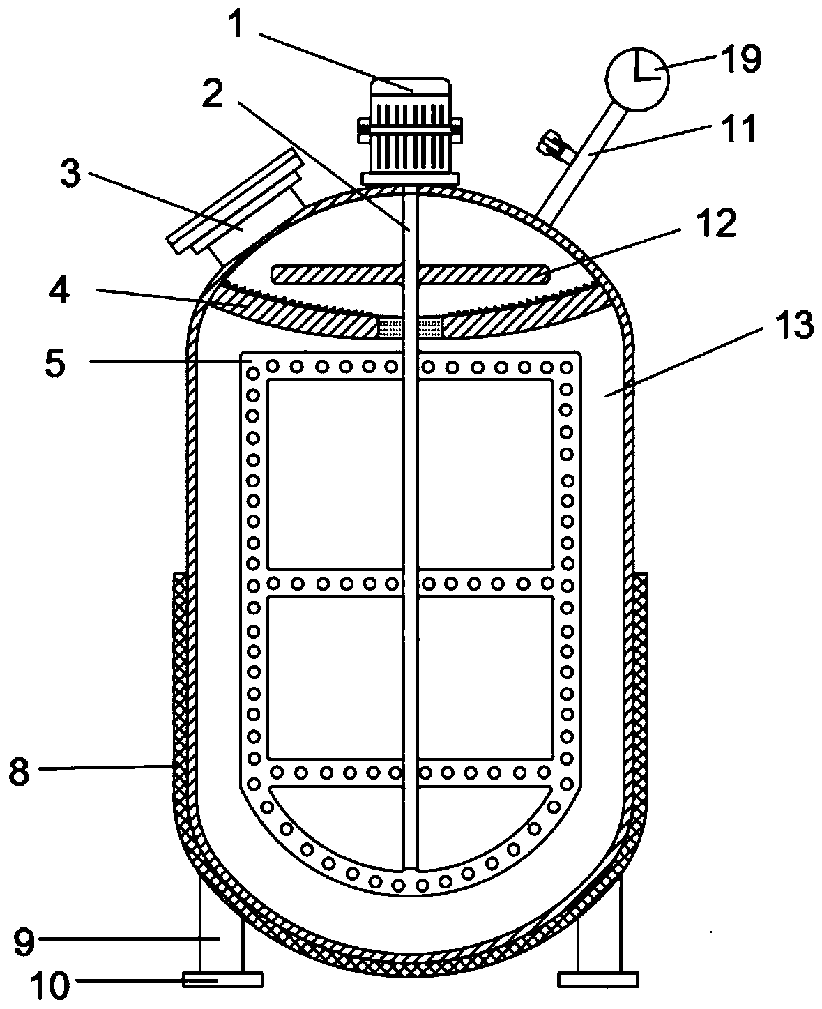
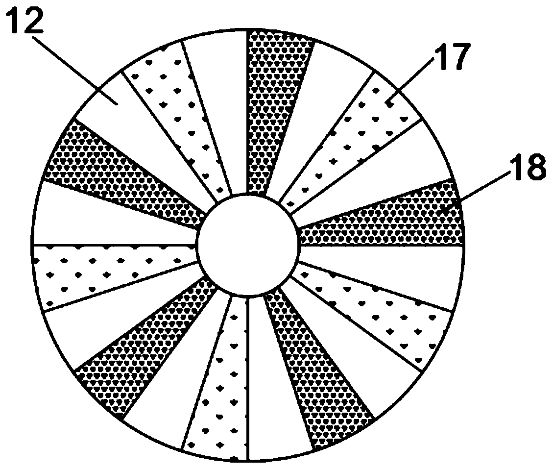
[0026] refer to Figure 1-3 , a high-efficiency reaction kettle for chemical production, including a tank body 13, the top outer wall of the tank body 13 is connected with a motor 1 through screws, the output shaft of the motor 1 is fixed with a rotating shaft 2 through a coupling, and the upper side of the outer wall of the rotating shaft 2 The turntable 12 is connected by a key, the bottom of the outer wall of the turntable 12 is welded with brushes 17 and spikes 18 alternately, the upper side of the inner wall of the tank body 13 is welded with a grinding disc 4, the upper part of the outer wall of the grinding disc 4 is welded with grinding thorns, and the lower side of the outer wall of the rotating shaft 2 The stirring paddle 5 is fixed by screws, and the outer wall of the stirring paddle 5 is evenly opened with flow holes.

[0027] In the present invention, the feed pipe 3 is fixed on the left side of the top outer wall of the tank body 13 by screws, and the inside of t...

Embodiment 2

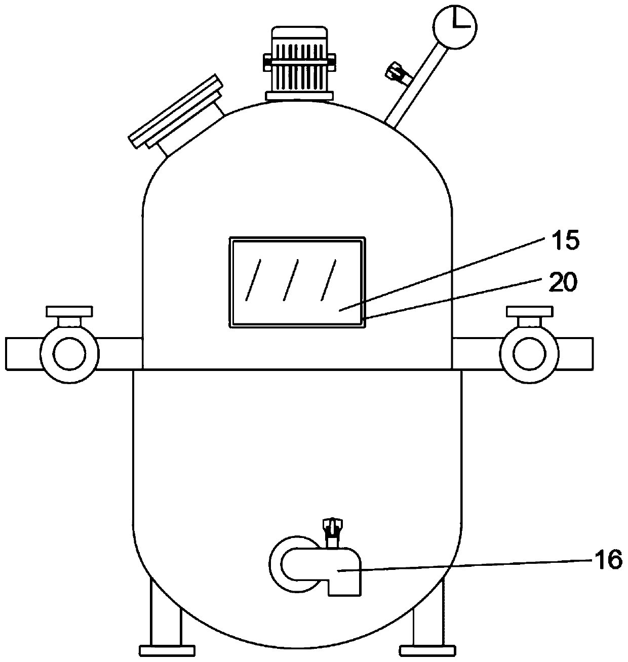
[0034] refer to figure 2 and Figure 4 , a high-efficiency reaction kettle for chemical production, the inner wall of the lower half of the tank body 13 is provided with a heating chamber, the inner wall of the heating chamber is welded with a heating layer 7, and the outer walls of both sides of the tank body 13 are respectively provided with a water inlet pipe 6 and an outlet pipe 14, Moreover, the outer walls of the water inlet pipe 6 and the water outlet pipe 14 are connected with electromagnetic valves through clamps.

[0035] Working principle: When the material enters the lower side of the tank body 13 through the feed hole of the turntable 4 and stirs, the water inlet pipe 6 and the water outlet pipe 14 are opened, and the hot water enters the inner heating layer 7 of the lower side of the tank body 13 from the water inlet pipe 6, and then flows from the Emit in the outlet pipe 14, make the hot water evenly flow in and out, keep the heating uniform when the material ...


PUM


Abstract

The invention discloses an efficient reaction kettle for chemical production. The efficient reaction kettle comprises a tank body, a motor is connected to the outer wall of the top of the tank body through screws, a rotating shaft is fixed to an output shaft of the motor through a coupler, a rotating disc is connected to the upper side of the outer wall of the rotating shaft through a key, and brushes and spikes are welded to the bottom of the outer wall of the rotating disc at intervals; a grinding disc is welded to the upper side of the inner wall of the tank body, grinding thorns are weldedto the upper portion of the outer wall of the grinding disc, stirring paddles are fixed to the lower side of the outer wall of the rotating shaft through screws, and through-flow holes are evenly formed in the outer walls of the stirring paddles. Materials are ground through the rotary disc and the static grinding disc, particles of the materials are refined, the reaction efficiency of the materials in the reaction kettle is improved, the materials in the reaction kettle are evenly heated through a heating layer, a jacket, a water inlet pipe and a water outlet pipe, the reaction time is shortened, and the reaction efficiency of the materials in the reaction kettle is improved.

Description

technical field [0001] The invention relates to the technical field of chemical production equipment, in particular to a high-efficiency reaction kettle for chemical production. Background technique [0002] The reaction kettle is a common equipment in the chemical production process. It is widely used in petroleum, chemical, rubber, pesticide, dye, medicine, food, and is used to complete the pressure of vulcanization, nitration, hydrogenation, alkylation, polymerization, condensation and other processes. container. The broad understanding of the reaction kettle is a stainless steel container with physical or chemical reactions. The structural design and parameter configuration of the container are carried out according to different process conditions. The design conditions, process, inspection, manufacturing, and acceptance must be based on relevant technical standards to achieve process requirements. Unique heating, evaporation, cooling and low-speed high-speed mixing rea...

Claims


Application Information

Patent Timeline
Patent Type & Authority Applications(China)
IPC IPC(8): B01J19/18B01J19/00B01F7/32B01F15/06B02C19/00B02C23/00B01F27/96
CPCB01J19/18B01J19/0013B02C19/0012B02C23/00B01F27/96B01F35/92B01F2035/99
Inventor 张杰
Owner 湖北菲特沃尔科技有限公司
Why Eureka
Try Eureka