
Power battery thermal runaway protection method, device and system

A power battery and protection system technology, applied in the field of vehicle safety, can solve problems such as extrusion, puncture, thermal runaway accidents, effective handling, and insufficient reliability, and achieve the effect of avoiding expansion and thermal runaway accidents

Active Publication Date: 2020-02-25
SAIC MOTOR
View PDF16 Cites 9 Cited by
  • Summary
  • Abstract
  • Description
  • Claims
  • Application Information

AI Technical Summary

Problems solved by technology

[0004] (1) Insufficient independence: To monitor the temperature of the power battery pack through the BMS, it is necessary to ensure the reliable operation of the BMS and ensure the normal operation of the power supply, communication, acquisition, and programs of the battery management system
The actual accident analysis shows that the BMS cannot work normally in the early stage of the thermal runaway accident, which makes the BMS unable to effectively deal with the thermal runaway accident in time, which leads to the expansion of the thermal runaway accident;
[0005] (2) Insufficient real-time performance: BMS monitors the temperature during the operation of the power battery pack, and statistically analyzes thermal runaway accidents. Some thermal runaway accidents occur during the shutdown of the power battery pack. The main reason is the external short circuit caused by the external environment, squeeze, pierce;
[0006] (3) Insufficient reliability: BMS judges whether thermal runaway occurs by monitoring the temperature parameters of the power battery
It has been proved by practical application that the dominant factors of power battery thermal runaway include not only abnormal temperature, but also dominant factors such as gas and smoke concentration. Therefore, only relying on temperature parameters to judge thermal runaway makes the detection results less reliable

Method used


Image

  • Power battery thermal runaway protection method, device and system
  • Power battery thermal runaway protection method, device and system
  • Power battery thermal runaway protection method, device and system

Examples


Embodiment Construction

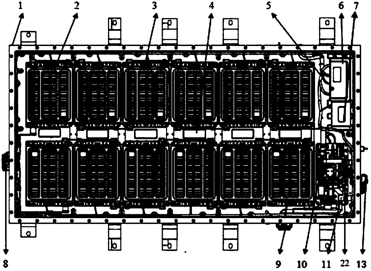
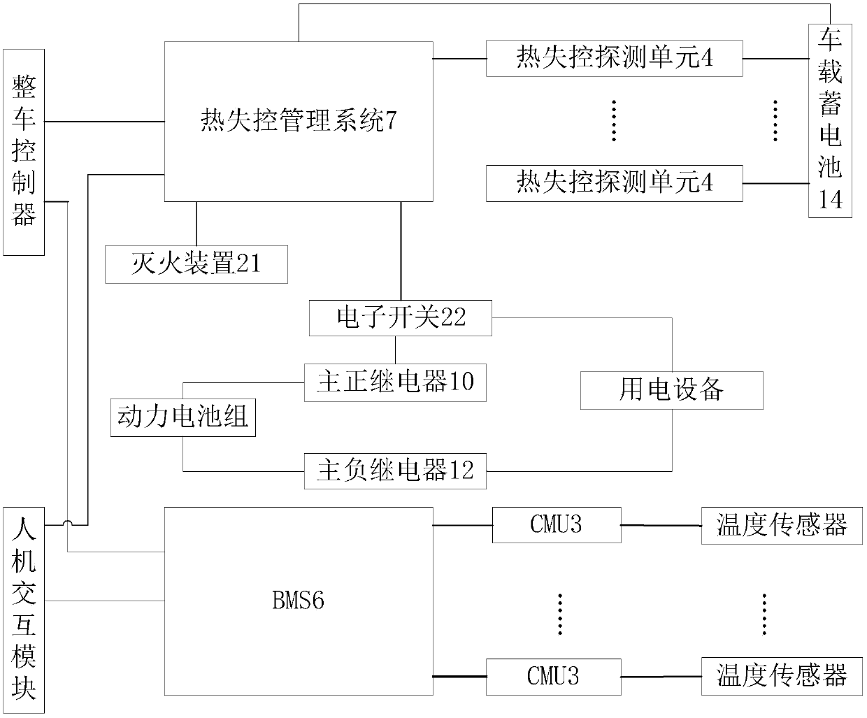
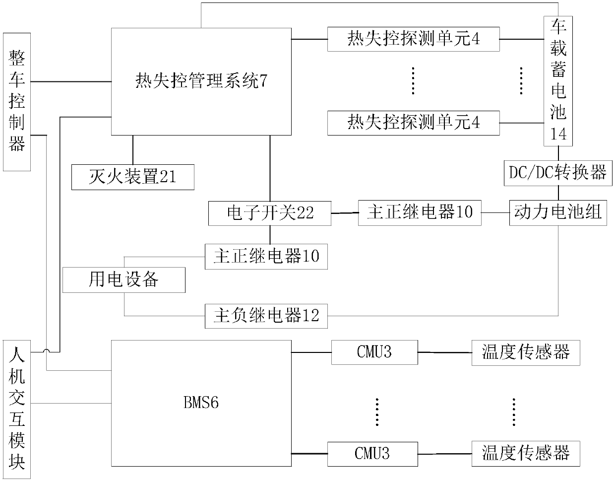
[0045]In order to solve the problem that the BMS cannot monitor the power battery pack to prevent thermal runaway when the vehicle is powered off. The present invention monitors the power battery pack when the vehicle is powered off by setting a thermal runaway management system, and then cuts off the power output of the power battery pack in time when the power battery pack has thermal runaway and implements fire extinguishing on the power battery pack through the fire extinguishing device In order to avoid the expansion of thermal runaway accidents; further, by connecting the electronic switch in series with the power output circuit of the power battery pack and controlled by the thermal runaway management system, when the main relay of the power output circuit of the power battery pack has a sticking failure, Ensure that the power output of the power battery pack is cut off; and the thermal runaway detection of the power battery pack is also performed through the thermal run...


PUM


Abstract

The invention belongs to the field of vehicle safety, and provides a power battery thermal runaway protection method, device and system. The method comprises the steps: detecting whether a vehicle isin a power-off state or not in real time, and controlling a thermal runaway detection unit to work when the vehicle is in the power-off state, so as to detect the temperature, gas concentration and / orsmoke concentration of a power battery pack; and judging whether the power battery pack has a thermal runaway fault or not according to the data detected by the thermal runaway detection unit, if so,cutting off the power output of the power battery pack, and controlling a fire extinguishing device to extinguish the fire of the power battery pack. Therefore, by monitoring the thermal runaway condition when the power battery pack stops running, thermal runaway accidents caused by external short circuit, overstock, puncture and the like due to the influence of the external environment during the running stopping period of the power battery pack are avoided.

Description

technical field [0001] The present invention relates to the field of vehicle safety, and more specifically, to a thermal runaway protection method, device and system for a power battery. Background technique [0002] The safety of power batteries has a crucial impact on new energy vehicles, and the control of thermal runaway of power batteries has become a major technical point of new energy vehicles. The existing control scheme for power battery thermal runaway is mainly to monitor the temperature of the power battery through BMS (BATTERY MANAGEMENT SYSTEM, battery management system). Whether the temperature of the battery pack reaches the critical value, if the temperature reaches the critical value, the BMS drives the relay in the power battery pack through the communication system, cuts off the main circuit of the power battery pack, and stops the operation of the power battery pack. [0003] It has been proved by practical application that the temperature monitoring of...

Claims


Application Information

Patent Timeline
Patent Type & Authority Applications(China)
IPC IPC(8): H01M10/635H01M10/42H01M10/48A62C3/07A62C3/16
CPCH01M10/635H01M10/425H01M10/482A62C3/07A62C3/16H01M2010/4271Y02E60/10
Inventor 徐启祥
Owner SAIC MOTOR
Learn More